Commissioning/application notes
CU1521-xxxx, CU156128 Version: 2.5
If the opposite direction of rotation is set, the subsequent behavior depends on the EtherCAT master. The
scanned CU15x1 may be inserted at a different position in the topology, or an INIT_VPRS error message of
the EtherCAT master may occur.
Frame size in Ethernet mode
In Ethernet mode only a frame size from 64 to 1522 bytes is supported.
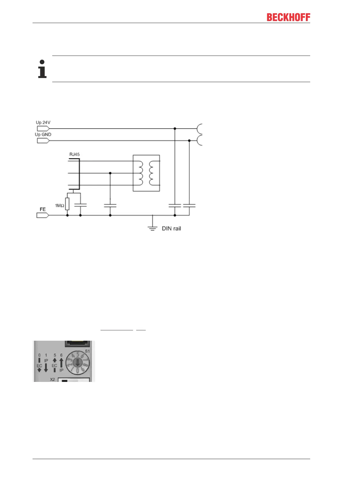
Earthing/Shielding
The FE contact on the supply socket must be directly connected to the mounting rail contact. During
assembly, always take care of a conductive connection to the mounting rail.
Fig.18: Internal earthing concept
Firmware update
A firmware update via EtherCAT is not possible for devices of the CU15x1 series
General notes
The CU15x1 deals with setting the rotary switch when the supply voltage is applied, unless the rotary switch
is in an invalid position. In this case the CU15x1 deals with the setting when the rotary switch reaches a valid
position for the first time.
If the rotary switch is moved during valid operation, the CU15x1 does not alter its function but indicates this
state through its LED, see Diagnostics [}24]. The switch setting must be rectified before the voltage is re-
applied!
Fig.19: Rotary switch
Slanting installation of the optical fiber socket in the CU15x1 reduces the bending radius of the optical fiber
cable during connection in the control cabinet (Fig. Slanting installation of the optical fiber socket).