Commissioning/application notes
CU1521-xxxx, CU1561 45Version: 2.5
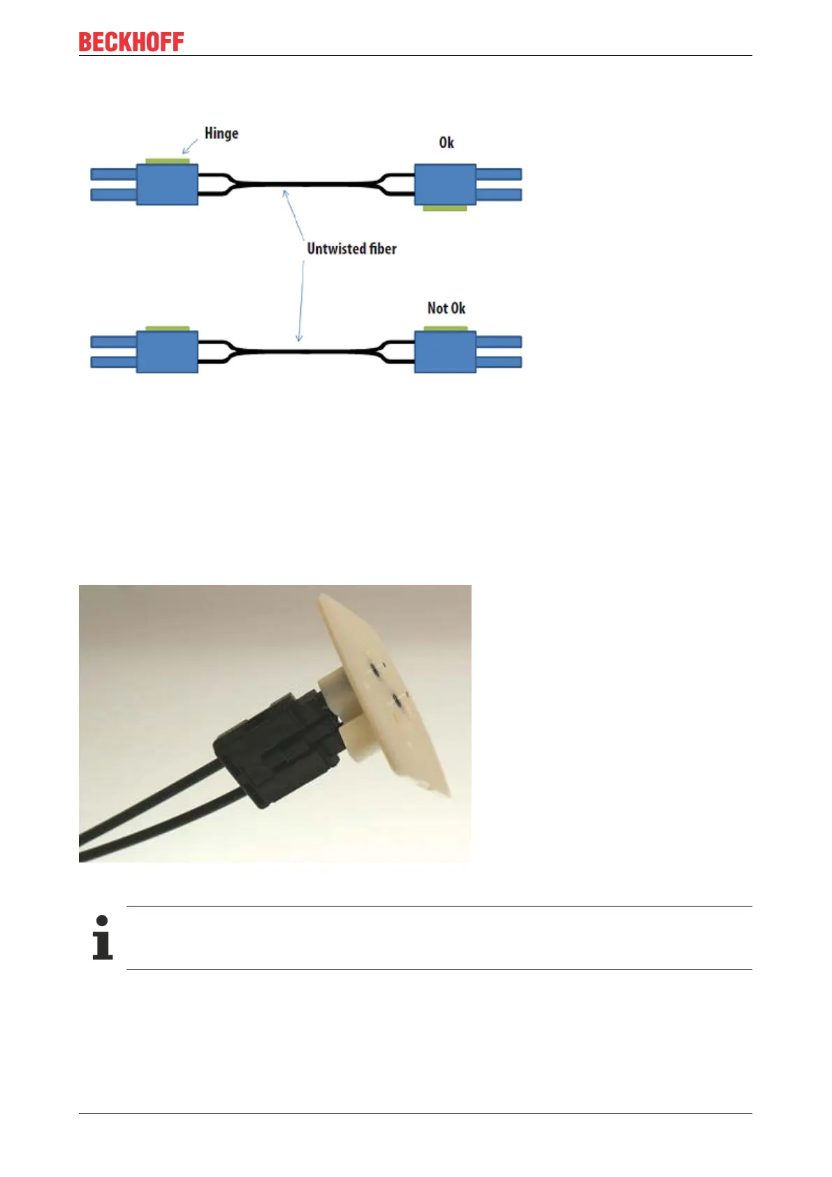
When inserting the wires into the connector ensure the optical channels are crossed (Tx1 --> Rx2; Tx2 -->
Rx1). The 'nose' at the connector hinge can be used as a guide (Fig. Correctly connected optical channels).
Fig.33: Correctly connected optical channels
3. Grinding and polishing
Any fibers protruding more than 1.5mm from the connector should be shortened with a cutter knife or a pair
of scissors.
Now push the connector fully into the sanding gauge, so that the ends to be polished protrude from the lower
side (Fig. Sanding gauge with protruding fiber ends). The sanding gauge is suitable for polishing one or two
simplex connectors or a duplex connector.
Fig.34: Sanding gauge with protruding fiber ends
Wear indicator
The wear indicator of the sanding gauge consists of four points on the underside. The sanding
gauge should be replaced when one of these points is no longer visible.
Now press the sanding gauge onto the abrasive paper with uniform pressure and as perpendicular as
possible. In order to achieve a uniform result, use the abrasive paper in the form of a figure of 8 (Fig.
Polishing in the form of a figure "8"), until the fibers are flush with the sanding gauge. Then clean the sanding
gauge and the connector from below with a soft, dry cloth.