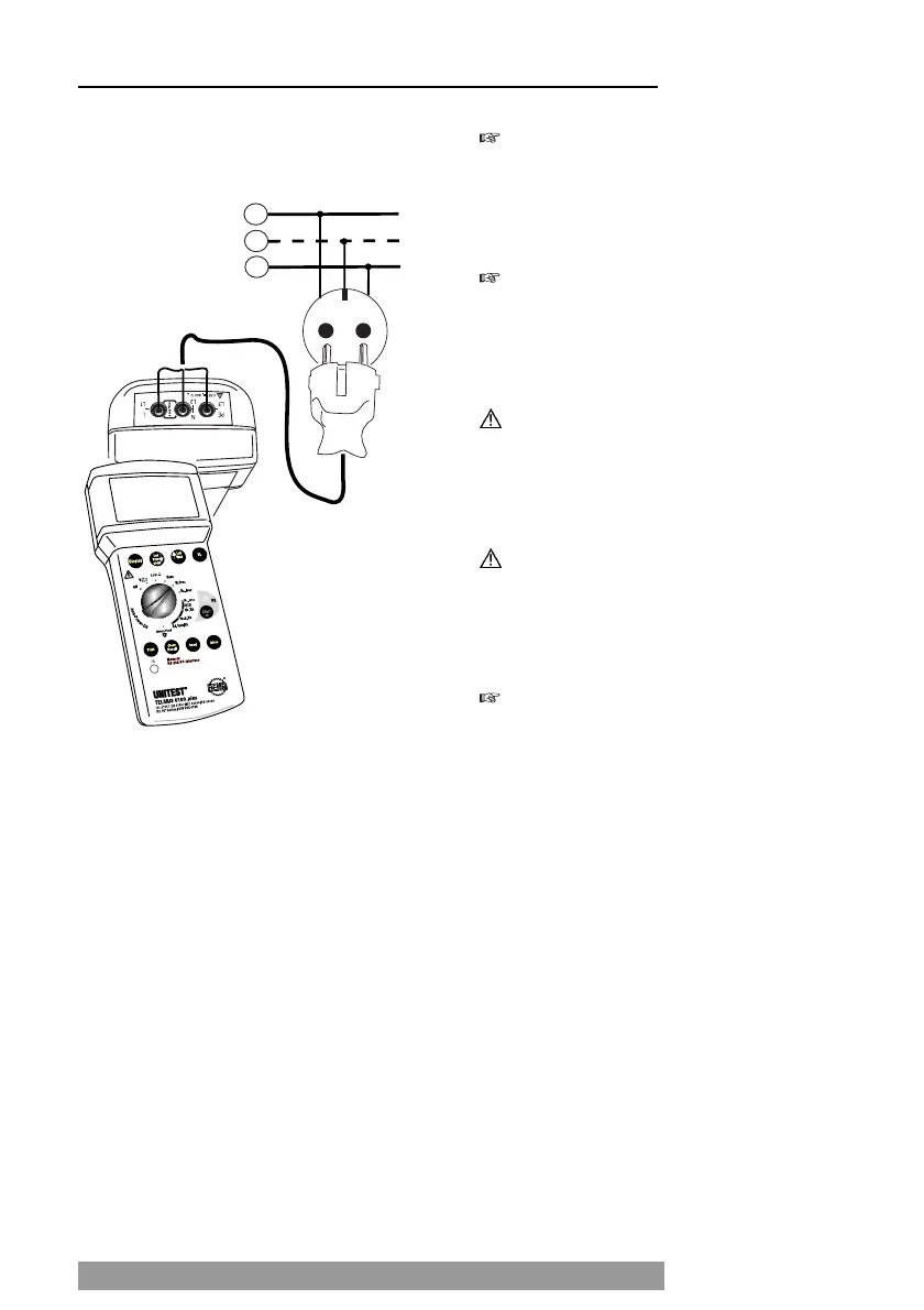
Plug the plug into the socket under test.
Select the Mains Internal Resistance function
(RI, IK) using the "Measurement Function" rota-
ry dial (32).
Select the contact voltage limit by pressing the
'VL' key (24).
The socket is continuously checked for faults.
If the "turn plug by 180°” symbol (7) is di-
splayed on the screen, you are advised to eit-
her turn the Schuko-plug or the exchange the
L and N connectors at the instrument.
If the symbol for socket error (6) is displayed
on the screen, we are dealing with a socket wi-
ring error. If a voltage exceeding the pre-selec-
ted contact voltage limit is present between N
and PE, 'UB>UL' (4) is displayed on the screen.
To perform a complete socket test, touch the
contact electrode PE (25) and observe the di-
splayed values on the screen. A valid result may
only be achieved when touching the contact
electrode PE (25)!
You are dealing with a PE error, if the error sig-
nal is audible and the 'Attention' symbol (1),
and 'Socket Error' symbol (6) are displayed.
I.e., either the PE is not connected or a high vol-
tage (phase) is present at PE.
The measurement may only be started if the
socket is not faulty and if the measurement
adapter has been connected by respecting cor-
rect polarity.
Press the "Start" key (26) to start the measure-
ment. During the measurement ' - ' is displayed
on the screen.
Read the measurement result displayed on the
screen. The mains internal resistance is di-
splayed in the large result field (12). The short-
circuit current IPSC is displayed in the small re-
sult field (14). .
16
Mains Internal Resistance Measurement / Short Circuit Current Measurement
 Loading...