Time-delayed residual current devices trip at
nominal residual current within 130…500ms,
for double nominal fault current within
60…200 ms. Such RCDs are im-plemented as
main residual current protection devices
(please refer to IEC 61008-1) and are marked
with the symbol .
The contact voltage represents the voltage pre-
sent during an insulation error between two si-
multaneously touchable components.
At a measuring circuit without probe, available
voltages between PE and earth can influence
the measurement..
At use of the N-conductor as probe, the N-con-
ductor should be check first for all of correct
and low-ohm connection to neutral point of sy-
stem. An available voltage of the N conductor
to the earth can influence the measurement.
Leakage currents by preconnected loads can
influence the measuring.
Attached loads or operating supplies which
contains capacitors or circulating machines
can elongate the trip time.
Any test and measurement procedures in cir-
cuits equipped with residual current devices
should only be performed after having con-
sulted the operator terminals (data processing
systems, material processing, motors, etc.).
For measurements on earthed sockets or
equipment with protective conductor connec-
tion, the protective earth must be checked for
correct connection by touching contact elec-
trode "PE". If an error is indicated via the sock-
et error symbol (6), the PE connection must be
checked ! The user may only start the test, once
the protective conductor is properly connect-
ed.
Prior to testing, we recommend all loads are
switched off as they could falsify the measure-
ment result.
The protective earth must be free of external
voltage for the RCD test. However if an extra-
neous voltage is present, the instrument only
indicates the voltage VC having been generat-
ed by the measurement. The measurement in-
terruption caused by excess of VL by VC is only
generated by the actual voltage present be-
tween the neutral conductor (N) and the pro-
tective earth (PE).
5.7.1 RCD – Measurement of Contact
Voltage UB and the Earthing Resistance
RE without RCD Tripping
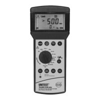
The instrument UNITEST TELARIS 0100 plus offers
the facility to test contact voltage or the earthing re-
sistance with reference to the nominal current of the
RCD within supply systems equipped with RCDs wi-
thout causing the RCD to trip. The contact voltage
measurement is performed at approximately 1/3 of
the pre-selected nominal current. The measured
contact voltage is then extrapolated to nominal trip
current and finally displayed.
The contact voltage is determined by short-term
mains loading, the measurement current flows wit-
hin the PE and L conductors.
To achieve a precise measurement result, we
advise to switch off all loads or to disconnect
them from the mains, and to ensure that the
UUT is faultfree.
Leakage currents within the current circuit fol-
lowing the residual current circuit breaker may
falsify the measurement, like any possible vol-
tage present between PE and ground, and any
possible voltage present between neutral con-
ductor and ground.
22
RCD – Measurement of Contact Voltage UB

 Loading...