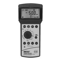
Read the measurement result displayed on the
screen. The loop resistance is displayed in the
large result field (12). The short-circuit current
Ik is displayed in the small result field (14).
If the resistance measured exceeds 1999 Ω,
the attention symbol (1) and '>1999 Ω' are di-
splayed on the screen. As there is no valid me-
asurement value for ZL, it is not possible to cal-
culate and display the short-circuit current IK.
'---' is displayed in the small result field (14
The short-circuit current is calculated using the
mains voltage and the loop impedance. Here,
the value 230V is used for the mains voltage if
the mains voltage amounts close to 230V. If the
measurement value deviates considerably
from 230V, the actual measurement value is
used to calculate the short-circuit current.
Supply system preloading and voltage fluctu-
ations can lead to erroneous measurement re-
sults. Therefore, you are advised to perform
several measurements and to compare the me-
asurement results.
If many measurement are performed allowing
only "short breaks", the internal over tempera-
ture protection of the Telaris 0100 plus is trig-
gered and the symbol for excessive tempera-
ture (20) is displayed on the screen. The
following mains internal resistance measure-
ment may only be started once the instrument
has cooled down and the symbol (20) has di-
sappeared from the screen. Thus, any damage
to the instrument can be avoided.
You may store the measurement result by pres-
sing the 'Store' key (27).
If you wish to store the condition of a faulty
socket, please press the "Start” key (26) first.
After hearing the "Error Signal” you may press
the "Store” key (27).
5.7 General Information about RCD Tests
The contact voltage UB and the trip time t required
by the RCD to disconnect the subsequent current
circuit from the mains represent important meas-
urement units for the assessment of an RCD.
For this reason, IEC 60364 prescribes that
a) the maximum allowable value for the contact
voltage (25V/50V) may not be exceeded within
any system during tripping at nominal residual
current.
b) the RCD must trip within a time limit of 300ms.
The task of an residual current device (RCD) con-
sists in switching off a system within a defined time
period after an error prior the contact voltage reach-
es the permissible limit value of 25V / 50V.
The system testing should be started by carrying
out a visual inspection, in particular of the protec-
tive earth connection.
1. Within the IT system, the protective earth con-
ductor does not have to be connected with the
PEN but with the protective earth connection.
2. The protective earth conductor must be connect-
ed to the PEN prior to the RCD within the TN sys-
tem.
3. An insulation measurement as described in Sec-
tion 5.3 must be performed. In particular it must
be proofed, that there is no connection between
N and PE following the RCD.
4. Proof regarding the low impedance connection of
equipotential bonding conductors in compliance
with Section 5.2 must be available.
21
General Information about RCD Tests

 Loading...