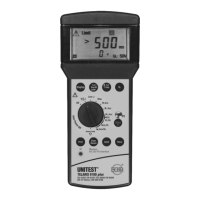
You are dealing with a PE error, if the error sig-
nal is audible and the 'Attention' symbol (1),
and 'Socket Error' (6) are displayed. I.e., either
the PE is not connected or a high voltage
(phase) is present at PE.
The measurement may only be started if the
socket is not faulty and the measurement adap-
ter has been connected by respecting correct
polarity.
Press the "Start" key (26) to start the measure-
ment. During the measurement ' - ' is displayed
on the screen.
If a contact voltage UB is generated between
conductors N and PE exceeding the pre-selec-
ted contact voltage limit VL, the measurement
is interrupted and the 'Attention' (1), 'UB>UL'
(4) symbols are displayed on the screen.
If the contact voltage measured exceeds the
50V or 100V measurement range, the attention
symbol (1) and '>50V' or '>100V' are display-
ed on the screen..
The trip time tA is displayed in the large result field
(12). The measured trip time tA and the contact vol-
tage with reference to the trip current may be called
for display by pressing the 'display' key (21).
If the RCD trips during the measurement, the
symbol for socket error (6) is displayed. If the
RCD already trips during the preliminary test,
the "Attention” symbol (1) is displayed in addi-
tion. In this instance, please check whether the
correct nominal trip current has been selected.
Possibly, the current preload of the PE is at
such a high level that the RCD trips cirrectly
caused by the test, or the RCD itself might even
be faulty.
If the trip time tA measured is not within the ad-
missible range (tA: < 300ms; 50% I∆N ? IR
∆100% I∆N), the 'Attention' symbol (1) is di-
splayed and for the display of the respective
level the symbol for 'Limit Value exceeded' (3)
appears. To make a safe decision whether the
RCD is defective, a trip test should be perfor-
med at nominal trip current (tA, UB). For exam-
ple, an RCD is in perfect condition when having
a trip time > 300ms at 60 % I∆N, and when te-
sting at nominal trip current (at 100% I∆N)
showing however a trip time < 300ms.
Failure for RCD tripping could be a wrong set-
ting of the nominal current or a faulty RCD.
Supply system preloading and voltage fluctu-
ations can lead to erroneous measurement re-
sults. Therefore, you are advised to perform
several measurements and to compare the me-
asurement results.
If many measurement are performed allowing
only "short breaks", the internal over tempera-
ture protection of the Telaris 0100 plus is trig-
gered and the symbol for excessive tempera-
ture (20) is displayed on the screen. The
following mains internal resistance measure-
ment may only be started once the instrument
has cooled down and the symbol (20) has di-
sappeared from the screen. Thus, any damage
to the instrument can be avoided.
You may store the measurement result by pres-
sing the 'Store' key (27).
If you wish to store the condition of a faulty
socket, please press the "Start” key (26) first.
After hearing the "Error Signal” you may press
the "Store” key (27).
28
RCD Test with Rising Residual Current (Ramp Method), Trip Current (I , ta/VC

 Loading...