10 2600 Quick Start Guide 11
2600 Controls
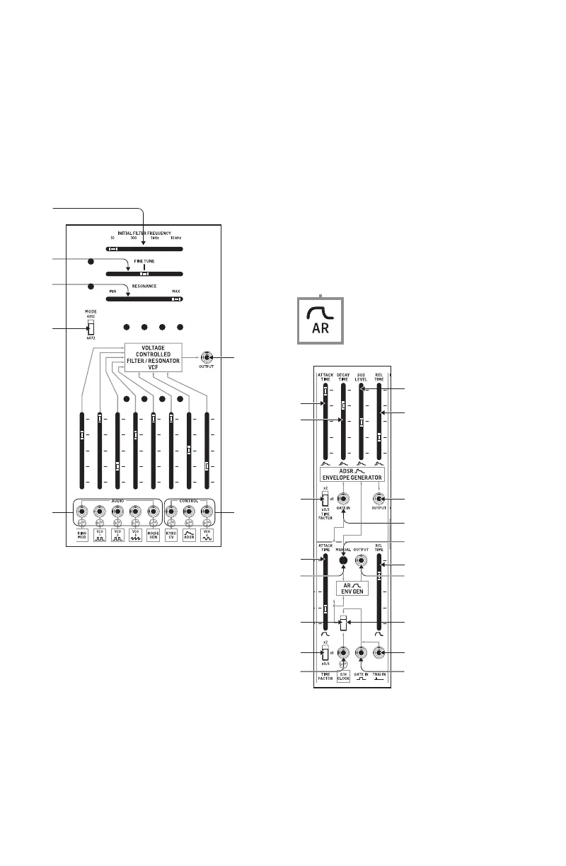
Voltage Controlled Filter (VCF)/Resonator Section
The VOLTAGE CONTROLLED FILTER (VCF)/RESONATOR uses a low-pass lter with
a variable cuto frequency (FC) and resonance (Q). The VCF can be controlled by
panel controls or by voltage control signals.
(9) INITIAL FILTER FREQUENCY – This slider sets the low-pass lter to four
coarse frequency points at 10 Hz, 100 Hz, 1 kHz and 10 kHz, which can then
be adjusted via the FINE TUNE slider.
(10) FINE TUNE – Use this slider to make further adjustments up or down from
the lter cuto point set by the INITIAL FILTER FREQUENCY slider.
(11) RESONANCE – Use this slider adjusts the lter’s Q setting. At the MAX
setting, the frequency curve below the lter cuto becomes a sharp and
the lter will ring in response to sharp pulses that pass through the lter.
(12) MODE (4012/4072) – This sliding switch chooses between two classic
lter circuits, the 4012 lter (the original lter design with a 16 Hz
maximum cuto frequency) and the 4072 lter (which had a lower
maximum cuto frequency at 11 Hz).
(13) OUTPUTS – This jack allows you to route out the VCF output for use in
other areas of the synthesizer via a cable with a 3.5 mm connector.
(14) AUDIO – These inputs allow you to route in audio signals via cables with
3.5 mm connectors. Each of these inputs breaks the pre-wired connection
when a connector is inserted into the jack.
(15) CONTROL – Use these inputs for external control voltage signals via
cables with 3.5 mm connectors. Each of these inputs breaks the pre-wired
connection when a connector is inserted into the jack.
AR/ADSR Envelope Generator Section
These two envelope generators produce controllable, transient waveforms for
use mainly with the Voltage Controlled Filter (VCF) and the Voltage Controlled
Amplier (VCA).
The AR (Attack-Release) transient generator creates an adjustable transient
envelope every time the generator is activated by a gate or trigger voltage. The
voltage transient is shaped by the ATTACK TIME and RELEASE TIME sliders, and
the AR transient envelope is available at all pre-wired connections with this label:
(16) ATTACK TIME – This slider controls the shape of the note attack up to an
initial xed peak when a key is depressed or a gate/trigger control voltage
enters the circuit.
(17) RELEASE TIME – Use this slider to control the envelope shape following
the key release or release of the gate/trigger voltage.
(15)
(13)
(26)
(25)
(29)
(16)
(18)
(33)
(19)
(22)
(27)
(28)
(30)
(31)
(32)
(17)
(21)
(20)
(23)
(24)
(18) MANUAL – Press this button to manually produce a gate signal to trigger
both the AR and ADSR circuits.
(19) TIME FACTOR (x2/x1/x0.5) – Use this sliding switch to choose between
three basic time durations for the overall length of the envelope.
(20) ROUTING SWITCH – Use this sliding switch to choose between the S/H
CLOCK pre-wired connection, the GATE IN input or the TRIG IN input. The
signal chosen at this switch is also routed through to the ADSR generator.
(21) OUTPUT – Use this jack to send out an additional AR voltage envelope for
use where a pre-wired AR connection is not available.
(22) S&H CLOCK – This input allows you to substitute another external signal
for the Sample & Hold circuit’s output via a cable with a 3.5 mm connector.
(23) TRIG IN – This input jack allows you to route in a trigger voltage via a
cable with a 3.5 mm connector.
(24) GATE IN – This input jack allows you to route in a gate voltage into the AR
and ADSR circuits via a cable with a 3.5 mm connector.
The ADSR (Attack-Decay-Sustain-Release) transient generator works similarly to
the AR generator, but this circuit creates a more detailed voltage transient every
time the generator is triggered by a gate or trigger voltage. The voltage transient
is shaped by the ATTACK TIME, DECAY TIME, SUS LEVEL and REL TIME sliders, and
the ADSR voltage transient is available at all pre-wired connections with this
label:
(25) ATTACK TIME – This slider controls the shape of the note attack up to an
initial xed peak when a key is depressed a gate/trigger control voltage
enters the circuit.
(26) DECAY TIME – Use this slider to control how quickly the envelope drops
from the initial xed peak.
(27) SUS LEVEL – This slider controls the level at which the envelope holds
after the initial decay following the xed peak.
(28) REL TIME – Use this slider to control the envelope shape following the key
release or release of the gate/trigger control voltage.
(29) TIME FACTOR (x2/x1/x0.5) – Use this sliding switch to choose between
three basic time durations for the overall length of the envelope.
(30) OUTPUT – Use this jack to send out an additional ADSR voltage envelope
for use where a pre-wired ADSR connection is not available.
(31) GATE IN – Use this jack to route in a gate signal via a cable with a 3.5 mm
connector.
(32) MANUAL – Press this button to manually produce a gate signal to trigger
both the AR and ADSR circuits.
(33) ROUTING SWITCH – Use this sliding switch to choose between the S/H
CLOCK pre-wired connection, the GATE IN input or the TRIG IN input. The
signal chosen at this switch is also routed through to the ADSR generator.
Voltage Controlled Amplier Section
The Voltage Controlled Amplier (VCA) oers further tone-shaping possibilities
in parallel with the Voltage Controlled Filter (VCF) before both are blended in the
Mixer section. At maximum gain, the VCA passes signals through at unity gain. At
minimum gain, the VCA circuit will not pass a signal.
(34) INITIAL GAIN – This slider sets the overall gain for the VCA circuit.
(35) AUDIO – Use these inputs to route audio signals into the VCA and adjust
the signal gain using the slider immediately above the inputs. Inserting
the 3.5 mm connectors into the jacks will disable the pre-wired VCF and
RING MOD connections.
(36) CNTRL (LIN/EXPL) – These inputs can accept control voltage signals
via cables with 3.5 mm connectors. The left input has a linear response,
while the right input features an exponential response. Inserting 3.5
mm connectors into these jacks will disable the pre-wired AR and ADSR
connections.
(37) OUTPUT – Use this output to route the nal VCA signal out for use where a
pre-wired VCA signal is not available.
(38)
(39)
(40)
(44)
(45)
(41)
(46)
(43)
(42)
 Loading...