12 2600 Quick Start Guide 13
Mixer/Reverb Section
The Mixer section accepts two inputs that are balanced via the two sliders and
then summed into a single signal. After being summed, the combined signal can
then be panned before going to the stereo outputs. The Mixer section is pre-
wired with inputs from the VCF and VCA.
NOTE: 2600 uses a digital reverb, while BLUE MARVIN features a real,
on-board spring reverb.
(38) AUDIO – Use these two inputs to route audio signals into the Mixer via
cables with 3.5 mm connectors. Inserting 3.5 mm connectors into these
jacks will disable the pre-wired VCF and VCA connections.
(39) POST-ATTENUATOR OUTPUTS – These two outputs allow you to send
signals out immediately following the attenuator sliders, which means the
sliders can be used to attenuate audio or control voltage signals for use
elsewhere.
(40) POST-MIXER OUTPUT – This input breaks the signal connection from the
Mixer to the PAN slider when a 3.5 mm connector is inserted. Use this input
to route in an outside signal for use by the PAN slider. The Mixer output still
goes to the Reverb circuit via a pre-wired connection.
(41) PAN – Use this slider to place the summed Mixer signal where desired in
the left-right stereo eld before nal output.
(42) MIXER OUT – This output is an additional Mixer output that taps the pre-
wired Mixer connection which feeds into the Reverb circuit.
(43) REVERB OUT – This output taps the right Reverb signal for use elsewhere.
(44) LEFT INPUT – Use this input to add an additional signal to the Reverb
circuit’s left output. The additional signal will be summed with the left
Reverb output and panned hard left in the stereo eld.
(45) RIGHT INPUT – Use this input to add an additional signal to the Reverb
circuit’s right output. The additional signal will be summed with the right
Reverb output and panned hard right in the stereo eld.
(46) L OUTPUT/R OUTPUT – The nal stereo left-right outputs each have
matching parallel pairs of ¼” and 3.5 mm connections. The ¼” outputs
can be used to send the nal mix to external ampliers, speakers or other
processing equipment. The parallel 3.5 mm jacks can be used to send the
left and right outputs to other synth circuits for further processing.
Keyboard/Portamento Section
The Keyboard section determines how the built-in Low Frequency Oscillator (LFO)
unit works with an external keyboard.
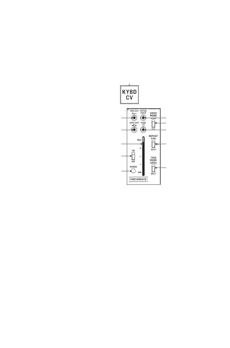
The keyboard control voltage is available as a pre-wired connection wherever
you see this label:
(47) TRIG OUT – Use this output to send out a trigger control voltage for use
elsewhere via a cable with a 3.5 mm connector.
(48) GATE OUT – This output can be used to send out a gate control voltage via
a cable with a 3.5 mm connector.
(49) UPPER VOICE – This output sends out a control voltage based on the
highest note being played on the keyboard while in DUO voice mode.
(50) KYBD CV – This output sends out the complete keyboard control voltage
signal for use elsewhere.
(51) VOICE MODE(MONO/DUO) – Use this sliding switch to determine
whether the keyboard plays one voice at a time (MONO) or two voices
simultaneously (DUO).
(52) REPEAT (KYBD/OFF/AUTO) – Use this sliding switch to control how
the keyboard sends trigger signals. When the switch is set to the KYBD
position, the keyboard will send out repeating trigger pulses as long a key
is held down. In the AUTO setting, the keyboard will send out a stream of
trigger pulses based on the synthesizer’s LFO setting. When the switch
is in the center OFF position, the keyboard will generate only one trigger
pulse per key press (i.e., the keyboard will revert to “normal” keyboard
functionality).
(53) TRIG MODE (SINGLE/MULT) – When this switch is set to SINGLE, the
keyboard will only generate a trigger pulse when a key is played while no
other keys are being played. In MULT mode, the keyboard will generate
a trigger pulse every time any key is pressed down, even if previously
pressed keys are held down.
The Portamento function allows one pitch to change gradually to a second pitch
a predetermined rate.
(49)
(51)
(50)
(52)
(53)
2600 Controls
(54) ON/OFF – This switch turns the Portamento function on or o.
(55) MOMEN – Pressing this button temporarily activates the Portamento
function for as long as the button is held down.
(56) MAX/MIN – This slider controls the strength of the Portamento eect.
The MAX setting provides the most gradual and smooth eect.
Low Frequency Oscillator (LFO) Section
The unit includes a purpose-built Low Frequency Oscillator (LFO) primarily meant
to function with a keyboard. The LFO has a pre-wired connection to VCO1, as
indicated by this label:
(57) LFO (SAW) – This output allows you to route a sawtooth LFO signal out for
use elsewhere via a cable with 3.5 mm connectors.
(58) LFO (SQUARE) – This output allows you to route a square wave LFO signal
out for use elsewhere.
(59) EXT VIB IN – This input allows you to route in an external LFO signal for
blending with the delayed LFO sine wave.
(60) LFO (SINE) DELAYED – This output can be used to send out a copy of the
LFO’s pre-wired sine wave output for use elsewhere. This output signal is
delayed at a rate controlled by the VIB DELAY slider.
(61) LFO SPEED – Controls the base speed of the LFO oscillation.
(62) VIB DELAY – This slider controls the amount of delay applied to the LFO
sine wave.
(63) VIB DEPTH – This slider controls the intensity of the vibrato eect created
by the delayed sine wave LFO signal.
Envelope Follower Section
The Envelope Follower generates an output voltage based on an input signal,
depending on the average amplitude of the input signal. The generated control
voltage’s characteristics can be adjusted to create various eects when the
output is routed to the VCF, VCA or the VCOs.
The input signal can be adjusted via the Preamp, which feeds into the Envelope
Follower via a pre-wired connection.
The Envelope Follower’s output does not have a pre-wired connection to other
sections of the synthesizer.
(64) PREAMP INPUT – Use this input to route an external signal into the
Preamp via a cable with a 3.5 mm connector.
(65) RANGE (X1000/X100/X10) – Use this sliding switch to determine the
base amount of amplication applied to the input signal and then adjusted
via the GAIN slider.
(66) GAIN – This slider determines how strongly the input signal is amplied.
(67) PREAMP OUTPUT – This output sends out a copy of the Preamp signal for
use elsewhere in the synth.
(68) PREAMP INPUT – This input allows you to bypass the Preamp and route
an external signal directly into the Envelope Follower. Alternately, the
input signal can be blended with the signal coming into the Envelope
Follower via the pre-wired connection.
(69) SENSITIVITY – This slider controls the sensitivity of the Envelope Follower
circuit.
(70) OUTPUT (ENVELOPE FOLLOWER) – Use this output to route the nal
Envelope Follower signal out for use elsewhere in the synthesizer via a
cable with a 3.5 mm connector.
(59)
(60)
(62)
(63)
(70)
(69)
(68)
 Loading...