12 WING RACK Quick Start Guide
Quick Start Guide 13
WING RACK Overview
Talkback
The talkback mic level, Dim attenuation and other monitor settings can be adjusted on the SETUP>MONITORS page. By clicking on the TALKBACK>SETUP button, the
talkback signals can be sent to dierent destinations.
Either Channel 40 or Aux 8 can be used as the processing channel for the talkback signal. Processing can be applied as needed. Any input can be assigned to the
selected talkback channel.
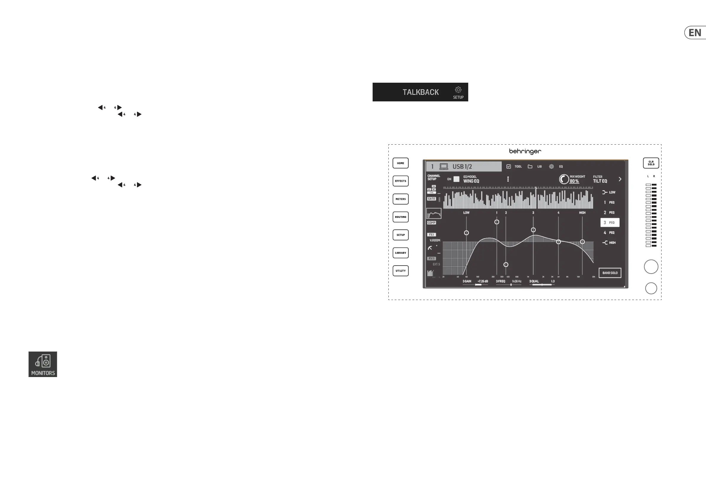
Main Display
The seven buttons to the left of the display and the VIEW buttons located in each major section of the top panel allow access to dierent settings screens. Anoverview
of each screen is presented in Chapter 5.
The large stereo meter will either display the main bus or solo bus levels. The CLR SOLO button will release all channels and buses that are active in the solo bus.
BUSES/MAINS
Press the button to toggle between the following layers:
• • Buses 1-16.
• • Main buses 1-4 and matrices 1-8.
Both layers are organized in groups of four channels. Each bus/matrix has its respective level, mute, and solo controls.
Navigate the buses/matrices with the and buttons . Holding these buttons down immediately goes to the rst and last page, respectively. Thecurrent page
number is indicated by the LED screen above the and buttons.
DCA/MUTE
Press the button to toggle between the following layers:
• • DCA groups 1-16.
• • Mute groups.
The DCA groups are shown in groups of four on the scribble strips with a dedicated fader (assigned to the respective knob), mute and solo controls.
Navigate the DCA groups with the and buttons . Holding these buttons down immediately goes to the rst and last page, respectively. The current page
number is indicated by the LED screen above the and buttons.
When the mute groups layer is active, groups 1 to 8 are assigned to the 8 buttons otherwise used for mute and solo control.
CUST/TRANS
Press the button to toggle between the following layers:
• • Custom controls.
• • USB player transport controls (when USB ash drive is inserted).
• • WING-LIVE transport controls (when SD card is inserted).
When the CUSTOM CONTROLS button is active, pressing the VIEW button opens the page to edit the CUSTOM CONTROLS. You can assign a wide range of parameters to
the 4 knobs and 8 buttons in the Control Section.
USB connector
A USB type-A connector allows a ash drive to be plugged directly into the console for saving or loading data. This allows you to back up your show les or load your
usual setup on a rented WING console.
This USB connection allows recording and playback of two- or four-channel-WAV audio les. The port can also charge a portable device such as a phone or tablet. Flash
drives connected to the USB port can be disconnected whenever the ACCESS light has turned o.
Monitoring
A dedicated knob controls the headphone output level of the bus MONITOR B (headphone output) found in the source group “Monitor” in the ROUTING screen. Further
monitoring section settings are found on the SETUP>MONITORS page.
To use the headphone connectors on the console the monitor signals must be routed to the corresponding outputs 1/2, 3/4, 5/6 and 7/8. These outputs are labeled
with a headphone symbol on the output routing page.
If near-eld monitors are being used, a physical volume control can be achieved in two ways:
1. Routing the MONITOR B (headphone) bus to the physical outputs to which the speakers are connected.
2. Assigning the MONITORING>SPEAKERS parameter to a knob in the CUSTOM CONTROLS screen.