10 11X32 CORE DIGITAL RACK MIXER Quick Start Guide
(1) (3) (4) (5) (6) (7) (8) (9) (10) (11)
(2)
(12) (13) (15) (16) (17)(14) (18)
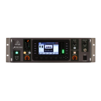
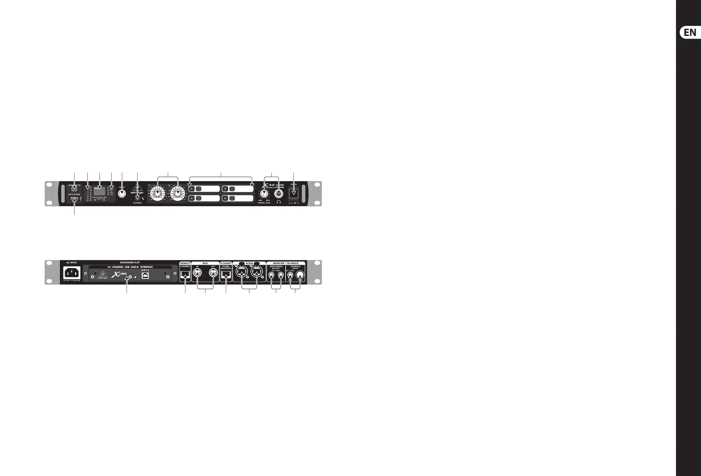
X32 CORE DIGITAL RACK MIXER Controls
(EN) Step 2: Controls
(1) SCENE/SETUP button toggles between
Scenes Recall (green LED) and Channel
Selector mode (LED o) with a short press.
Hold the button to enter Setup Mode
(green LED) and press the button again
to exit Setup Mode. The LED turns red to
indicate access on attached DATA/AUDIO
USB media.
(2) DATA/AUDIO input allows connection of
USB ashdrives for rmware updates,
loading/saving scenes and show les,
and playing back or recording WAV les.
(3) METER displays the input level of the
selected channel.
(4) DISPLAY shows the channel name and icon,
scene name, or setup page information.
(5) CHANNEL TYPE LEDs indicate which type of
channel is currently selected.
(6) SELECT knob navigates the display menus
and edits setup parameters. See the SELECT
Knob Functions section for details.
(7) TALKBACK button engages the external
Talkback mic input on the rear panel.
Details of the routing and operation can be
dened on the monitoring preferences page
of the control software.
(8) USER ASSIGNABLE ENCODERS adjusts
a predened variable parameter in
the software. Function to be dened in the
control software.
(9) USER ASSIGNABLE BUTTONS toggles
a predened on/o parameter in
the software. Function to be dened in the
control software.
(10) PHONES output and level allow audio
to be monitored directly from the unit.
Details of the audio content can be adjusted
in the monitoring preferences page of the
control software. While in Channel Select
Mode, push the Select encoder to toggle
Solo on and o.
(11) POWER button turns the unit on and o.
(12) X-USB interface card allows up to
32 channels of bidirectional audio to be
transmitted to and from a computer.
(13) ETHERNET connector allows full OSC-based
remote control of the X32 CORE.
(14) MIDI IN/OUT allows the unit to send and
receive MIDI commands via standard 5-pin
DIN cables.
(15) ULTRANET connector sends 16 channels of
audio to a P16 monitoring system.
(16) AES50 A and B connectors allow 96 channels
of bidirectional audio for connection to S16
digital snakes or other X32 family products.
The front panel LEDs will light green to
indicate proper sync, light red to indicate
a sync error, and remain unlit when no
connection is present. Shielded CAT-5e
cable should always be used for AES50
connections between X32 and S16 units.
(17) MONITORING OUTPUT jacks allow connection
of monitor speakers via balanced or
unbalanced ¼" cables.
(18) TALKBACK input accepts a dynamic
microphone via ¼" TRS jack. Adjust the gain
with the adjacent TRIM knob.