Beijer Electronics Frequency Inverter BFI-H3 KI00363B 2019-09
www.beijer.se www.beijer.no www.beijer.dk www.beijerelectronics.de www.beijerelectronics.com www.beijerelektronik.com.tr 16 (29
5.10 Control from a Modbus RTU master
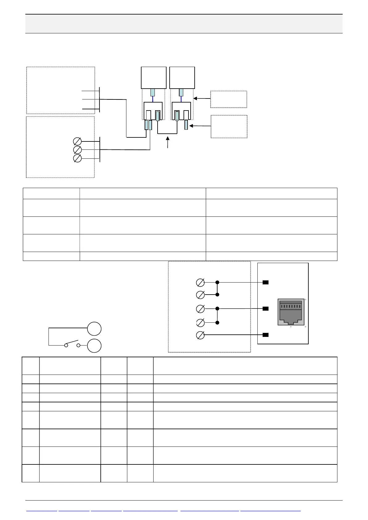
A Modbus RTU network with BFI-E3, BFI-H3 or BFI-P2 is connected as below:
Settings in BFI-H3 are speed setting is 115 200 bit/sec, 8 data bits, 1 stop bit, No Parity.
Hardware Function Comment
CAB 114 Shielded cable with one RJ45 and 3 wires marked
SDA, SDB and SG for screwte
Cable length 3 m. Modbus RTU- pin7 and Modbus
CAB 113 Shielded cable with one RJ45 for BFI and one 9-pole
Cable legth 3 m. Built-in 120 ohm resistor in D-sub
OPT-2-J45SP-BFI T-Connection of 2 serial cables into one drive. RJ45 male to BFI and 2 female RJ45 for network
To be put in the last BFI
Para-
meter
Name Default
settng
To be set
Function
63. First Drive should be stationnumber 1
P5-04
Data Format 0 0
0 or "n-1”= No Parity, 1 stop bit 1 or “n-2”= No parity, 2 stop bits
P5-05
Comm Loss Timeout 1,0
Drive behaviour if a communication command is not received within time
specified in this parameter.
P5-06
Comm Loss Action 0
0: Trip and coast to stop 1: Ramp to stop and trip;
2: Ramp to stop and no trip
P5-07
Fieldbus Ramp Ctrl 0
Decide which ramp for accelearation and deceleration to be used. 0: From
2
1
DI1: Startsignal
+24 VDC
DI1 must always be closed to start
Modbus master RTU
SG
SDB
BFI
RDB
SDA
RDA
Put termination switch in 100 ohm
8
7
3
1 8
BFI
CAB 113
Patchcable
Cat 6
Modbus master
X2 panel
CAB 114
RS485 + Pin1
OPT-2-
RJTRM-
OPT-2-
RS485 – Pin6
Modbus master
Nexto Express
D+
D-
GND
BFI


 To Next Page