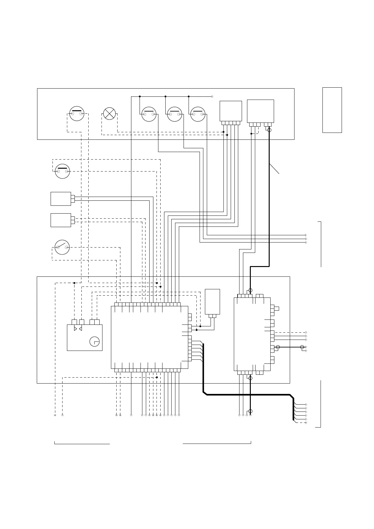
BV700
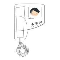
Camera
+
-
1
S
M
206
Lock
Release
203
Lock
Release
Trades
Button
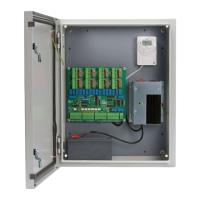
Door Panel Electrical Cupboard
Common Strap
1
2
3
(optional)
(optional)
Name
Lamp
Exit Button
*1
Alternative Locks
Door Monitor
Switch
(optional)
(optional)
or
Fire Switch
819S
Switching Unit
UPPER PCB
+
S
-
+
-
12V
CAMERA 1 ENG1
+
-
M
CAMERA 2
ENG2
+
-
-
+
S
M
+
-
M MS S
CAM
PHONE
X
LO
LI
O V
819S
Switching Unit
LOWER PCB
+
H
HC
-
12V
EXIT SPEECH
T
-
C
EXIT SPEECH
+
-
R L
PHONES
O
R
+
+
+
B
+
+
-
-
-
-
FAIL
SECR
FAIL
SAFE
DOOR
SW
LOCK
REMOTE
ENG
LAMP
+
H
-
T
-
C
O
R
+
+
+
B
+
+
-
-
-
-
LAMP
ENGDOOR
SW LOCK SECR
FAIL FAIL
SAFE
ZTX
DC
DOOR 1
DOOR 2
(719S)
M440
Power
Supply
-
+
12V
Diagram 5b : Wiring for a 2 Door 1 - 10 Way Bell View Video System
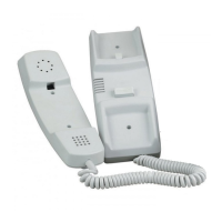
M61
Speech
unit
C
H
R
O
T
+
-
To second entrance
Call lines
I3 I2 I1
to each phone
To telephones (see diagram 5c)
Camera
Trades
Button
Door
Monitor
Switch
ROT Z V L
CAM
+
-
M S
75R Co-ax
Lock
Speech
Unit
Exit
Button
*1 Connect '+' to '1' to activate IR lamps.
*2 The Time Clock has an isolated contact.
Notes
2 DOOR
1-10
© 2000 Bell System (Telephones) Ltd.
Push
Buttons
Page 5 of 6
Time
Clock
-
+
12V
TS2000
NO
CO
*2