R
Randy MoralesSep 8, 2025
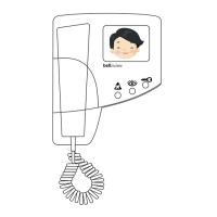
What to do if picture does not appear when Bell System bellview Intercom System phone is buzzed?
- MMichael GallegosSep 9, 2025
If the picture doesn't appear on your Bell System Intercom System when the phone is buzzed, consider the following: * Check for faults on the video coaxial cable, especially the 'M' and 'S' connections. * Ensure the camera is receiving adequate power by checking for 10V-15V across the Camera '+' and '-' connections. * Verify that the coaxial cable is a 75 type. * Confirm that the ‘Auto - Display’ DIP switch is set to ON. * Check for sufficient power to the '+' and '-' video supply on the phone, ensuring 10V-15V is present.