

B
Brett KennedySep 9, 2025
What to do if there is no picture when calling videophone on Bell System bellissimo Intercom System?
- WwilliamsjenniferSep 10, 2025
To solve the problem, make sure to check that the Auto display switch is on. See page 19.
What to do if there is no picture when calling videophone on Bell System bellissimo Intercom System?
To solve the problem, make sure to check that the Auto display switch is on. See page 19.
Why Bell System bellissimo lock release does not operate?
If the lock release on your Bell System Intercom System doesn't operate or clicks but doesn't open, consider the following: * Check for open or shorted connections to the lock release. * Voltage drop may occur if the cable is too thin. * The power supply might be resetting because the lock current is too high. * The lock release may be jammed due to overtight fitting.
How to fix a blank picture on Bell System bellissimo videophone?
If you are getting a blank picture when calling a videophone or pressing view on your Bell System Intercom System, it could be due to: * A broken or missing Video + or Video – wire. * Incorrectly configured cameras. * The call originating from an audio-only panel.
Why is the picture unstable and looks like a photographic negative on Bell System Intercom System?
If your Bell System Intercom System displays an unstable picture possibly with areas looking like a photographic negative, it is likely due to reversed Video + and – connections, or reversed M and S connections.
What to do if Bell System Intercom System videophone does not ring or flash when called?
If your Bell System Intercom System videophone isn't ringing or flashing when called, it could be due to several reasons: The videophone might be off hook or muted on full mute. There might be no power to the videophone; check if the red mute lamp flashes when the handset is picked up. The data wiring could have a fault, specifically Data A or B being broken. Also, if it's a separately powered videophone, the 0V to the controller might be missing.
How to fix a blank picture on Bell System Intercom System?
A blank picture on your Bell System Intercom System when calling a videophone or pressing view can stem from a few issues: a broken or missing Video + or Video – wire, incorrectly configured cameras (refer to CAM2 setting on page 18), or the call originating from an audio-only panel.
What to do if my Bell System bellissimo Intercom System videophone doesn't ring or flash when called?
If your Bell System Intercom System videophone isn't ringing or flashing upon receiving a call, consider these potential causes: * The videophone might be off-hook or fully muted. * There might be no power reaching the videophone; verify that the red lamp flashes when the handset is picked up. * A fault in the data wiring (Data A or B broken). * Separately powered videophone might be missing 0V to controller. * Pushbutton wiring error; test with short length at controller.
Why is there no speech from the Bell System bellissimo videophone to the entrance?
If there is no speech from the Bell System Intercom System videophone to the entrance, it could be due to a missing R core connection to the door controller, or broken Audio 1 or 2 connections.
Why is the 28V LED not lighting on the Bell System bellissimo Intercom System controller?
If the 28V LED on your Bell System Intercom System controller isn't lighting, temporarily remove the connection to the 28V+ output. If it then comes on, there is a short on the phone cabling. Alternatively, the 12V input connections may be reversed or missing.
Why Bell System bellissimo lock works only from exit button?
If the lock on your Bell System Intercom System operates from the exit button but not the test button or phone, a normally closed switch may have been used for the exit button.
Provides a general overview of the bellissimo video door entry system components and function.
Lists the key functionalities and capabilities of the 2-72 Way Video Entry System.
Explains the step-by-step process of a visitor call and resident response.
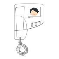
Describes the functions of the monitor controls, including contrast and volume.
Details the 'Auto Display' mode for automatic picture activation during a call.
Explains how to mute the videophone's ringing sound and its duration settings.
Describes how to view visitors without lifting the handset.
Explains the indicator for doors left open after a call.
Details how only one videophone can be active per call.
Notes that user activation is not available on multi-way systems.
Discusses the possibility of using one or two cameras, including CCTV integration.
Explains how to add additional videophones to a flat.
Covers support for fail-secure and fail-safe lock types, including magnetic locks.
Details the input for an exit button or fire switch for door release.
Explains the use of a time clock for tradesperson access.
Covers accessibility features for the Disability Discrimination Act.
Explains how to configure the system for multiple building entrances.
Details integration with gate controllers for shared entrances.
Describes using the videophone as a doorbell replacement.
Explains the slave output for operating external devices.
Lists the components included in various Bellissimo video kits.
Details available optional components and features for system expansion.
Provides guidance on optimal placement of the entrance panel for camera performance.
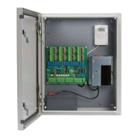
Specifies placement requirements for the door controller and its power supply.
Specifies placement requirements for the video controller and its power supply.
Details placement for the gate switch controller.
Explains how to overcome limitations with additional power supplies for videophones.
Outlines the system's 12V power supply needs and specific models.
Provides examples of controller and power supply configurations for different system sizes.
Details the required Cat5 cable type and specifications for system wiring.
Specifies maximum cable distances between video controllers and videophones.
Specifies maximum cable distances between door controllers and video controllers.
Specifies maximum cable distances between entrance panels and door controllers.
Specifies maximum cable distances for power supply connections.
Provides a checklist of required items and steps before installation.
General guidance on wiring procedures using Cat5 and 1mm² cables.
Instructions for mounting the entrance panel at the correct height and condition.
Instructions for wall mounting the videophone unit and securing it.
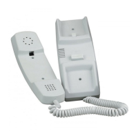
Details the BSA audio phone as an alternative extension unit.
Explains the connection and setting for electric door releases, including maglocks.
Important notes and considerations for fail-safe exit door releases.
Important notes and considerations for fail-secure exit door releases.
Details the function and wiring of the exit button input.
Explains the function of the door open switch for status indication.
Describes how to share a time clock signal across distributed areas.
Configuration of DIP SW1 (1-4) for talk time and videophone activation.
Configuration of DIP SW1 (5-8) for ringing time and call effects.
Configuration of DIP SW2 (1-3) for setting the lock release time.
Configuration of DIP SW2 (4-8) for various system functions like lock type and camera selection.
Configuration of DIP SW3 (1-8) for assigning numbers to cameras at the door.
Details jumper settings for camera termination, video gain, and DDA reassurance tones.
Details jumper settings for video gain and video termination on the BSC4 controller.
Configuration of SW6 rotary switch for videophone addressing on BSC4 controller.
Configuration of SW7 for adjusting address offset on BSC4 controller (Builds up to 6C).
Configuration of SW7 for adjusting address offset on BSC4 controller (Build 7 onwards).
Jumper configuration for extended addressing on BSC4 controller (Build 7).
Details special versions of BSC4 for addressing beyond standard ranges.
Jumper configuration for odd/even addressing of BSC4 outputs.
Configuration of DIP SW1 (1-4) for setting the mute duration on the videophone.
Configuration of DIP SW1 (5-8) for master/extension and auto display settings.
Details the jumper setting for video termination on the videophone.
Identifies common installation and wiring issues leading to system faults.
Provides tables for quick identification of power and call-related problems.
Troubleshooting guide for issues with lock release operation and maglocks.
Diagnoses and provides solutions for various video display issues.
Diagnoses and provides solutions for audio issues like feedback and low volume.
Technical specifications for the BSD8/72 door controller unit.
Technical specifications for the CAMBS-C colour camera.
Technical specifications for the BSC4 video controller.
Technical specifications for the BS Colour Videophone.
Technical specifications for the BSA audio phone.
Technical specifications for the Model 61 speech unit.
Technical specifications for the PS4 power supply unit.
Technical specifications for the 340C power supply unit.
Technical specifications for the battery-backed 840 power supply.
Technical specifications for the BSSW Gate Switcher.
Wiring instructions for connecting a local bell push to the videophone.
Explains the auxiliary ring output for DDA devices.
Provides options for camera wiring using twisted pair or coax cable.
Explains how to share a time clock signal using Cat5 wiring.
Wiring guide for connecting a Bellcode access controller to the system.
Wiring guide for connecting a Bell PAX1 proximity reader.
Wiring guide for connecting to gate controllers or other third-party access systems.
Wiring details for ACT 1000/2000/3000 proximity controllers.
Wiring details for ACT 100e proximity extenders.
Safety information and installation guidelines for the Model 840 power supply.
Safety information and installation guidelines for PS4 and 340C power supplies.
| Brand | Bell System |
|---|---|
| Model | bellissimo |
| Category | Intercom System |
| Language | English |