T M
Document NAE1018021 • 09.2014 • © Bender Inc. • Page 1/1 • Side 1/2Bender Inc. • USA: 800.356.4266 / 610.383.9200 / info@bender.org • Canada: 800.243.2438 / 905.602.9990 / info@bender-ca.com • www.bender.org
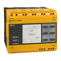
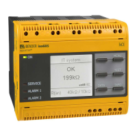
iso685
Installation Bulletin / Reference Guide
This document is intended as a reference guide for installing and using a BENDER iso685 ground fault
detector. This document includes installation, setup, and usage instructions. For complete details,
including installation, setup, settings, and troubleshooting, refer to the complete iso685 user manual.
This document is intended as a supplement and not a replacement to the complete user manual.
Only qualied maintenance personnel shall operate or service this equipment. These instructions
should not be viewed as sucient for those who are not otherwise qualied to operate or service this
equipment. This document is intended to provide accurate information only. No responsibility is as-
sumed by BENDER for any consequences arising from use of this document.
Installation
Mounting
The iso685 is a DIN-rail mounted device. See reverse side for dimensions.
!
DANGER
• Disconnect all power before servicing.
• Observe all local, state, and national
codes, standards, and regulations.
HAZARD OF ELECTRIC SHOCK,
EXPLOSION, OR ARC FLASH
Wiring - General
See gure 1 for basic wiring schematic. Line connections
(L1 and L2) may use the schematic below for systems be-
low 793 VAC or 1000 VDC. If a voltage coupler is used
to connect to the system, refer to the complete user
manual for the specic wiring diagram. Use minimum
AWG 24, maximum AWG 12 wire. When wiring is com-
plete, replace the terminal cover, making sure it clicks.
For more information, refer to the iso685 user manual.
In addition to the AC/DC 100-240 V supply voltage via
A1/A2 terminals, the device may also be powered by 24
VDC connected to the X1 connector. Refer to “Wiring -
Connector X1” for more information. Do not connect
both simultaneously.
Initial setup
Initial steps
• Select the language.
• Set the date and time.
• Set the system type - choose “DC” for DC systems, “AC” for single-phase AC systems, and
“3AC” for three-phase AC systems. In systems with power conversion, the system type that
should be selected should be the type at the point that the iso685 is connected.
• If a voltage coupler is used, select the correct one. Otherwise, select “None.”
Prole selection
Selecting a prole allows for an automatic setup of key system parameters required for opera-
tion. Select the prole that closest matches your application. Detailed descriptions of proles
are listed below. As a general guideline:
• For standard AC/DC power distribution with no power conversion, select “Power circuits.”
• For low voltage AC/DC control systems, select “Control circuits.”
• For systems with small- to mid-size inverters / VFDs, select “Inverter > 10 Hz.”
Select “High capacitance” if your system meets one or more of the following requirements:
• Very large distribution network (i.e. rated for 2000 A or more)
• System contains a high quantity of power conversion equipment (inverters / VFDs)
• The application typically includes high leakage capacitance, such as ships and solar arrays
Refer to the table below. NOTE: “Power conversion” refers to AC/DC or frequency conversion
equipment, including but not limited to rectiers, inverters, and variable frequency drives
(VFD/ASD).
1. Connection to 1Ø AC system
2. Connection to DC system
3. Connection to 3Ø AC system
4. Supply voltage connections (100 - 240
VAC) - 5 A fuses required
5. Line connections to monitored system
6. Connections to equipment / protective
ground
7. Alarm relay K1 - SPDT dry contact
8. Alarm relay K2 - SPDT dry contact
9. Switchable termination resistor - used
when connecting to Bender RS-485 bus
10. Ethernet port (currently inactive)
11. Connector X1 for digital inputs, RS-485,
analog output - see below
Wiring - Contacts
Using a normally closed or normally open contact utilizes two factors: wiring out of the proper
terminal, and setting the respective contact to normally energized or deenergized operation.
Refer to the chart below for relay conditions. Changing the energized state of the contact is
done via the “Relay 1” and “Relay 2” options (option “Mode”) found in the main menu.
Prole name
System specs (voltage,
frequency, leak. capacitance)
Application
Power circuits
Up to 690 VAC (15 - 460 Hz)
Up to 1000 VDC
0 - 150 μF
Standard AC and DC power distribution systems with no power
conversion equipment. Suitable for general applications.
Control circuits
Up to 230 VAC (15 - 460 Hz)
Up to 230 VDC
0 - 150 μF
Designed for low-voltage AC/DC control systems with no power
conversion equipment.
Generator
Up to 690 VAC (15 - 460 Hz)
Up to 1000 VDC
0 - 5 μF
Designed for generator monitoring applications with no power
conversion equipment, as well as systems with an extremely low
leakage capacitance.
High capacitance
Up to 690 VAC (15 - 460 Hz)
Up to 1000 VDC
0 - 1000 μF
Designed for applications with high leakage capacitances, inlcuding:
very large systems, ships, and solar applications.
Inverter > 10 Hz
Up to 690 VAC (10 - 460 Hz)
Up to 1000 VDC
0 - 20 μF
Use this prole when using standard power conversion equipment. If
the system contains a high amount of power conversion equipment,
select “High capacitance” prole.
Inverter < 10 Hz
Up to 690 VAC (1 - 460 Hz)
Up to 1000 VDC
0 - 20 μF
Use this prole when power conversion equipment is used that
continuously runs at an extremely low frequency.
GND
U
S
6A
A1/+ A2/-
11RX2X1 12 14 21 22 24
L1/+
L2 L3/- KE E
L1/+ L3/- KE E
L1
L2
GND
L1/+ L3/- KE E
L+
L-
GND
L1
L2
L3
1Ø AC System
DC System
1
2
3
4
5 6
7 8
91011
Digital interface Terminal Description
I1 I2 I3 AB
Q1
+
Q2 M+
X1
I1 Input 1
I2 Input 2
I3 Input 3
A RS-485 A
B RS-485 B
+ +24 V
Q1 Output 1
Q2 Output 2
M+ Analog output
Ground
I2
I3
A
B
M+
Q2
Q1
+
Reset
Standby
Installation (continued)
Wiring - Connector X1
The X1 connector provides a series of low-voltage inputs, including digital inputs, connections
to Bender RS-485 bus, and the analog output. Typically, these functions are used for remote
test, remote reset, analog output, and RS-485. The function that these inputs utilize must be
set in the menu. Refer to the menu ow chart on the reverse side for more information. Do not
connect the 24 VDC supply voltage and supply via A1/A2 simultaneously.
Relay operation setting Device alarm state Relay K1 State Relay K2 State
Normally de-energized mode
(N/D)
Non-failsafe mode
“N/O” in device settings menu
Energized in the alarm state
Relay will switch when the
alarm is activated.
Power ON, normal state
(no alarms)
11-12 CLOSED
11-14 OPEN
21-22 CLOSED
21-24 OPEN
Power OFF
11-12 CLOSED
11-14 OPEN
21-22 CLOSED
21-24 OPEN
Power ON, alarm state
11-12 OPEN
11-14 CLOSED
21-22 OPEN
21-24 CLOSED
Normally energized mode
(N/E)
Failsafe mode
“N/C” in device settings menu
Energized in the normal state
Relay will switch when the
alarm is activated, on device
startup, or when power to the
device is lost.
Power ON, normal state
(no alarms)
11-12 OPEN
11-14 CLOSED
21-22 OPEN
21-24 CLOSED
Power OFF
11-12 CLOSED
11-14 OPEN
21-22 CLOSED
21-24 OPEN
Power ON, alarm state
11-12 CLOSED
11-14 OPEN
21-22 CLOSED
21-24 OPEN
Example wiring for external
test, reset, and standby is
shown to the right. Note that
the correct option must be
set in the menu under “Func-
tion” for each digital input.