4
IR425-D4_D00039_04_M_ESEN / 03.2017
ISOMETER® IR425-D4
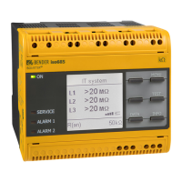
Indicating and operating elements
Terminal Connection
E, KE Connect the leads E and KE separately to PE.
A1, A2
Supply voltage U
S
(see nameplate) via 6 A fuse
11, 12, 14 Alarm relay K1
21, 22, 23 Alarm relay K2 (system fault relay)
T/R for combined external test/reset button
L1, L2 Connection to the system being monitored.
Elementos de indicación y manejo
Borna Conexiones
E, KE Conexión separada de E y KA al conductor PE
A1, A2
Tensión de alimentación U
S
(Ver placa de caracterí-
sticas) a través de fusibles 6 A
11, 12, 14 Relé de alarma K1
21, 22, 23 Relé de alarma K2 (Relé de fallo de sistema)
T/R Para tecla combinada externa de Test/Reset
L1, L2 Conexión al sistema IT que se desea vigilar
Ele-
mento
Función
Elementos del Display utilizados/
Display segments in use
Ele-
ment
Function
R1, R2
Valores de respuesta R
an1
, R
an2
R1, R2
Response values R
an1
, R
an2
1, 2 Relés de alarma K1, K2 1, 2 Alarm relay K1, K2
Punto encendido con luz intermi-
tente: Impulso de medida del IR425
Flashing dot:
Measuring pulse of the IR425
t, t
on
Retardo de arranque t
Retardo de respuesta t
on
t, t
on
Starting delay t,
Response delay t
on
off
Protección de palabra clave descon-
ectada
off Password protection disabled
M Memoria de errores activada M Fault memory activated
Modalidad de servicio de los relés
K1, K2
Operating mode of the relays K1, K2
Protección de palabra clave activada Password protection enabled
Ele-
mento
Función
Frontal del aparato/
Front of the device
Ele-
ment
Function
ON LED de servicio verde ON Power ON LED, green
AL1,
AL2
LED de alarma 1 se enciende (amarillo):
No se alcanza el valor de respuesta 1
LED de alarma 2 se enciende (amarillo):
No se alcanza el valor de respuesta 2
AL1,
AL2
LED Alarm 1 lights ( yellow):
value below response value 1
LED Alarm 2 lights (yellow):
value below response value 2
>1 MΩ
Display en servicio standard:
Resistencia de aislamiento R
F
> 1 M
>1 MΩ
Display in standard mode:
insulation resistance R
F
> 1 M
T,
Tecla de Test: Arrancar un auto-test
(> 1,5 s);
Tecla hacia arriba: Puntos del menú/Valores
T,
Test button: Starting a self test
(> 1.5 s);
Up key: menu items/values
R,
Tecla de Reset: Borrar la memoria de
errores (> 1,5 s);
Tecla hacia arriba: Puntos del menú/Valores
R,
Reset button: deleting the fault
memory (> 1.5 s);
Down key: menu items/values
MENU,
Arrancar el servicio de menú (> 1,5 s) ;
Tecla ENTER:
(< 1,5 s), punto del menú, punto de
sub-menú, Confirmar valor. (> 1,5 s)
retornar al nivel superior de Menú.
MENU,
Starting the menu mode (> 1,5 s) ;
Enter button:
(< 1,5 s) MENU, Sub menu item, con-
firm value. (> 1,5 s) back to the next
higher menu level.

 Loading...


