5
TBP202007deen / 10.2012
MK2418
Terminal strips
The MK2418-11 alarm indicator and test combination incorpo-
rates an upper and a lower terminal strip and the connections
PT1, PT2 at the rear of the device.
Version MK2418-12 only includes a lower terminal strip since all
messages are received via the BMS bus. These messages are re-
ceived from the insulation monitoring device 107TD47, an alarm
indicator MK2418-11 or the signal converter SMI470-9.
Cables
Supply voltage cable lengths U2/V2, when supplied by the mains
part AN450
The max. length of the connecting cables indicated above is the
length between U2/V2 of AN470 and U2/V2 of the last MK2418.
Commissioning
Prior to commissioning check proper connection of the device.
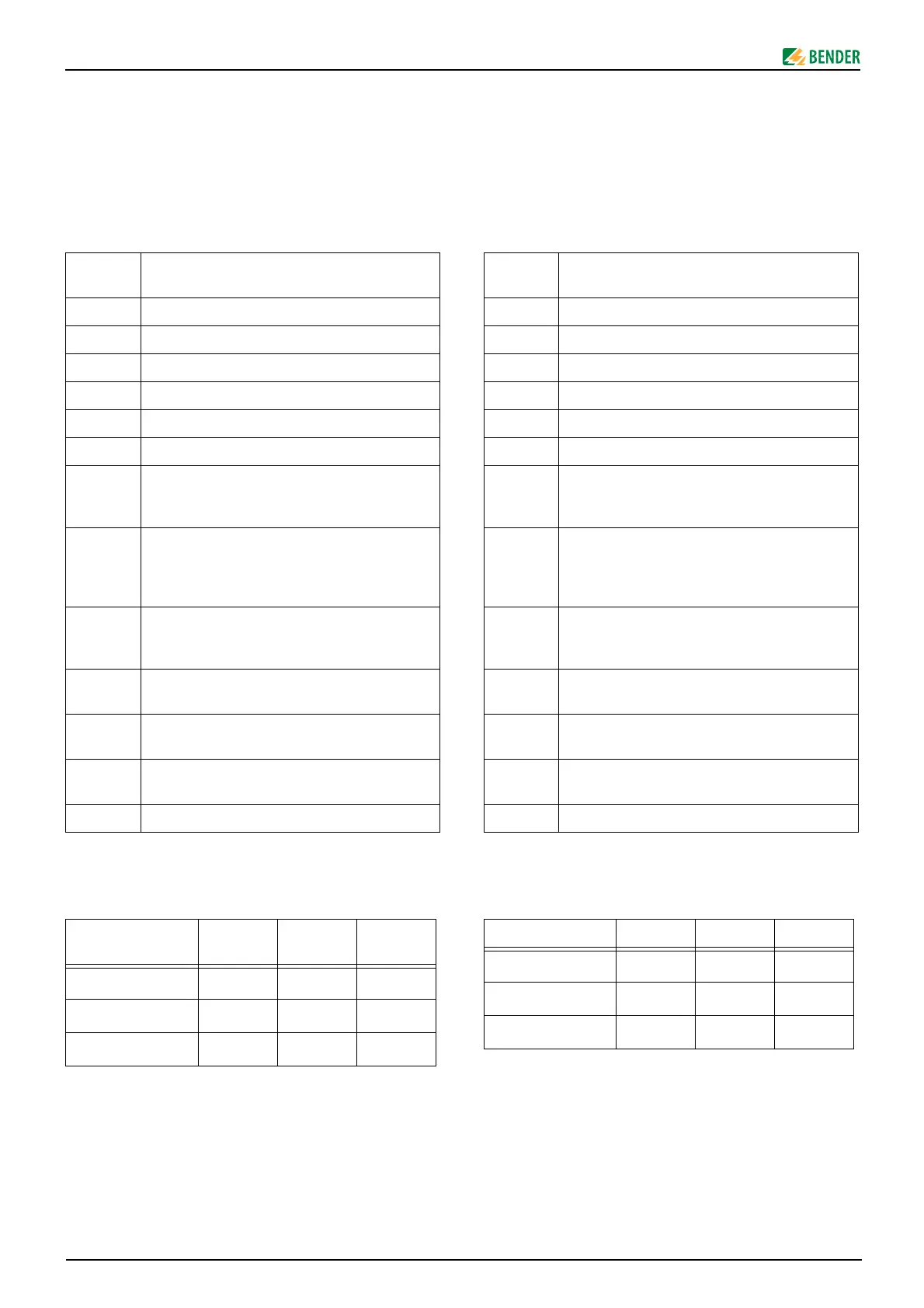
U2, V2 Supply voltage AC 20 … 28 V from 107TL47 or
AN450
A, B BMS bus
11, 12, 14 Changeover contact for collective message
0 Common connection for fault messages
IN1 Alarm message insulation fault from 107TL47
IN2 Alarm message overload from LSE470
IN3 Alarm message overtemperature from LSE470
IN4 Alarm message "Failure Line 1“ (preferred sup-
ply) from SUA470 (or another voltage monito-
ring relay)
IN5 Alarm message "Failure Line 2“ from contactor
relay K3 of the switchover module UM107ET (or
from a voltage relay of the second line in case of
other switchover modules).
IN6 Alarm message insulation fault operating thea-
tre lamp from 107TL47 (or another insulation
monitoring device).
IN7 Free digital input. Signals "CONTROL FAULT", if
activated.
IN8 Free digital input. Signals "FAILURE DISTRIBU-
TION BOARD", if activated.
M+, M- Input for the indication of the current IT system
transformer load, from LSE470.
PT1, PT2 Connection test button 107TL47
Wire cross section 1 MK2418 2 MK2418 3 MK2418
0,8 mm
2
750 m 400 m 150 m
1,5 mm
2
1500 m 700 m 250 m
2,5 mm
2
2300 m 1200 m 400 m
Klemmleisten
Die Melde- und Prüfkombination MK2418-11 enthält auf der Ge-
räterückseite eine obere und eine untere Klemmleiste, sowie die
Anschlüsse PT1, PT2.
Die Ausführung MK2418-12 enthält nur die untere Klemmleiste,
da sie alle Meldungen über BMS-Bus erhält. Diese Meldungen er-
hält es beispielsweise vom 107TD47, einer MK2418-11 oder vom
Signalumsetzer SMI470-9.
Leitungen
Leitungslänge für Versorgungsspannung U2/V2 bei Speisung
durch Netzteil AN450
Die genannten Leitungslängen gelten von U2/V2 des AN450 bis zu
U2/V2 der letzten MK2418.
Inbetriebnahme
Kontrollieren Sie vor der Inbetriebnahme den ordnungsgemäßen
Anschluss des Gerätes
.
U2, V2 Speisespannung AC 20 … 28 V von 107TL47
oder AN450
A, B BMS-Bus
11, 12, 14 Wechsler für Sammelmeldung
0 gemeinsamer Anschluss für Fehlermeldungen
IN1 Meldung Isolation Fehler von 107TL47
IN2 Meldung Überlast von LSE470
IN3 Meldung Übertemperatur von LSE470
IN4 Meldung „Ausfall Leitung 1“ (bevorzugte Ein-
speisung) von SUA470 (oder anderem Span-
nungsüberwachungsrelais)
IN5 Meldung „Ausfall Leitung 2“ vom Hilfsschütz K3
der Umschalteinrichtung UM107ET (bei anderen
Umschalteinrichtungen ggf. vom Spannungsre-
lais der 2. Leitung)
IN6 Meldung Isolation Fehler OP-Leuchte von
107TL47 (oder anderem Isolationsüberwa-
chungsgerät)
IN7 Freier Digitaleingang. Bringt Meldung „STEUE-
RUNGSFEHLER“, wenn er aktiviert wird.
IN8 Freier Digitaleingang. Bringt Meldung „AUSFALL
VERTEILER“, wenn er aktiviert wird.
M+, M- Eingang zur Anzeige der aktuellen Belastung
des IT-System-Transformators, von LSE470
PT1, PT2 Anschluss Prüftaste 107TL47
Leitungsquer-
schnitt
1 MK2418 2 MK2418 3 MK2418
0,8 mm
2
750 m 400 m 150 m
1,5 mm
2
1500 m 700 m 250 m
2,5 mm
2
2300 m 1200 m 400 m