3
MRCDB423_D00396_00_M_XXEN/06.2020
MRCDB423
terrupted. Since the installation has been switched off, residual current measurement is no longer possible.
The described device combination meets the requirements of IEC 60947-2 annex M for an MRCD protective
device.
The device function can be tested using the test button "T". Parameters are assigned to the device via the LCD
and the control buttons on the front panel; this function is password-protected.
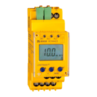
3.3 Standard display
The standard display shows the following:
• Residual operating current I
Δn2
• Response delays t
on2
• Residual current (present measured value)
The displayed values change periodically every 4 s.
3.4 Connection monitoring
The connections to the measuring current transformer are continuously monitored. In case of a transformer
connection fault, the output relays K1 and K2 switch, all LEDs flash. In addition, the error code "E.01" appears
on the display. Output relay K2 trips the circuit breaker, which disconnects the outgoing circuit to be moni-
tored. When the connection fault has been eliminated and the reset button "R" is pressed, the output relays K1
and K2 switch back to their initial position.
3.5 Manual self test
The device carries out a self test by pressing and holding the test button "T" (> 2 s), during which any internal
malfunctions are detected and displayed as an error code.
The output relays K1/K2 are switched so that the circuits breakers disconnects. After switching off, the
MRCDB423 carries out an offset calibration.
Due to this offset calibration, the self test must not be carried out
without a circuit breaker connected, which will shut down the installation. Otherwise, the measurement function
may be faulty after the self test has been performed.
This function prevents long-term drifting.
While pressing and holding the test button "T", all device-relevant display elements are shown.
3.6 Malfunction
In the event of an internal malfunction, all three LEDs flash. The display shows an error code (E.01…E.32). In
such cases, please contact the Bender Service.
3.7 Time delays t and t
on
The times t and t
on
described below delay the signalling of prewarning and main alarm via LEDs and the out-
put relays.
Start-up delay t
After the supply voltage U
s
has been switched on, the device is in alarm state, which means that the output
relays K1 and K2 are open and thus the installation is switched off. This parameter cannot be adjusted.
Response delay t
on1/2
When exceeding a residual operating current I
Δn1/2
, the MRCD requires the response time t
an
to output the
alarm. A set response delay t
on1/2
(0…10 s) adds up to the device-related operating time t
ae
and delays the
alarm signalling (total delay time t
an
= t
ae
+ t
on
).
Should the fault no longer persist during the response delay, the alarm signal drops out.
If I
Δn2
is set to 30 mA (protection of persons), the response delay t
on2
of K2
is automatically and invariably set to 0 s.