5
MRCDB423_D00396_00_M_XXEN/06.2020
MRCDB423
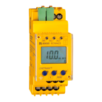
4.2 Wiring
Connect the device according to the wiring diagram.
5. Operation and settings
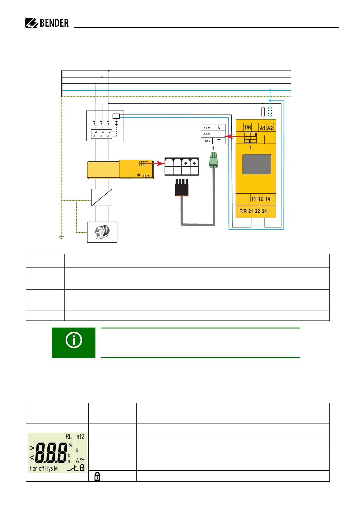
5.1 Display elements in use
The meaning of the display elements in use is listed in the table below.
Terminal Connections
A1, A2
Connection to supply voltage U
s
1 Socket for connection cable of measuring current transformer
T/R Connection for a combined external test and reset button
11, 12, 14 Output relay K1 (alarm)
21, 22, 24 Output relay K2
Warning: To comply with IEC 60947-2 Annex M, the MRCD423 must be
operated according to the N/C principle in combination with an
undervoltage release.
Display elements
in use
Element Function
I2
Residual operating current I
Δn2
in mA
I1
Prewarning I
Δn1
in % of I
Δn2
ton1,
ton2
Response delay t
on1
(K1)
Response delay t
on2
(K2)
M Fault memory active
Password protection enabled
> U
F 6A
L1
L2
L3
N
~
3~
CTBCx CTUB101
+12V -12V TGND
S1(k) S2(l)
CTX...
MRCDB423