6
MRCDB423_D00396_00_M_XXEN/06.2020
MRCDB423
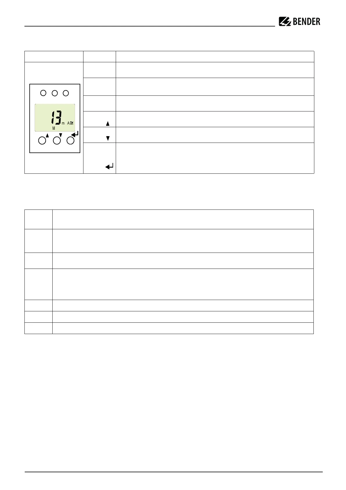
5.2 Function of the operating elements
Tab. 1: Function of the operating elements
5.3 Menu structure
Configurable parameters
Tab. 2: Configurable parameters
Device front Element Function
ON,
green
lights continuously: Power On LED,
flashes: system fault or malfunction of connection monitoring
AL,
TRIP
Alarm LED lights (yellow): Prewarning
I
Δn1
TRIP LED lights (yellow): Main alarm I
Δ
n2
13 mA
M
13 mA flow through the measuring current transformer,
Fault memory active
T, Standard display: (> 2 s): display test, self-test
Menu display: Arrow-up button (< 1 s)
R, Standard display:Reset button; (> 2 s): Erasing the fault memory
Menu display: Arrow-down button (< 1 s)
MENU,
Standard display:
Menu display: Enter button
(< 1 s): confirm menu item, submenu item and value.
(> 2 s): back to the next higher menu level
Menu
item
Adjustable parameter
AL
Query and set residual operating current:
– Residual operating current I2 (I
Δn2
)
– Prewarning I1 (I
Δn1
)
t
Set delays:
– Response delay t
on1
/t
on2
SEt
Set parameters for device control:
– Activate or deactivate password protection, change password
– Restore factory settings
– Service menu SyS locked
InF
Query software version
HiS
Query the alarm value saved first; Erase history memory
ESC
Exit menu and return to standard display