Bendix
Avionics
Division
ADF-T12C/D AUTOMATIC
DIRECTION FINDER SYSTEM
Installation
Manual
2-4. A. (2)
r
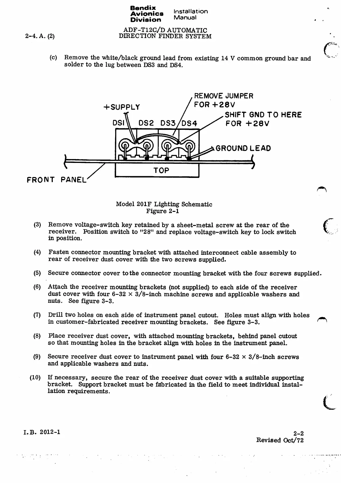
(c) Remove the white/black ground lead from existing 14 Vcommon groimd bar and
solder to the lug between DS3 and DS4.
R E M O V E J U M P E R
FOR +28V
+SUPPLY
SHIFT GND TO HERE
FOR +28V
DSI\\ DS2 DS3/DS4
.0
0
GROUND LEAD
k
Elt
TOP
FRONT PANEL
Model 201F Lighting Schematic
Figure 2-1
c
(3) Remove voltage-switch key retained by asheet-metal screw at the rear of the
receiver,
in position.
Position switch to "28" and replace voltage-switch key to lock switch
(4)
Fasten connector moimting bracket with attached interconnect cable assembly to
rear of receiver dust cover with the two screws supplied-
Secure connector cover to the connector mounting bracket with the four screws supplied.
Attach the receiver mounting brackets (not supplied) to each side of the receiver
dust cover with four 6-32 x3/8-inch machine screws and applicable washers and
nuts. See figure 3-3.
(5)
(6)
Drill two holes on each side of instrument panel cutout. Holes must align with holes ^
in customer-fabricated receiver moimting brackets. See figure 3-3.
Place receiver dust cover, with attached mounting brackets, behind panel cutout
so that mounting holes in the bracket align with holes in the instrument panel.
Secure receiver dust cover to instrument panel with four 6-32 x3/8-inch screws
and applicable washers and nuts.
(7)
(8)
(9)
If necessary, secure the rear of the receiver dust cover with asuitable supporting
bracket. Support bracket must be fabricated in the field to meet individual instal¬
lation requirements.
(10)
L
I.B. 2012-1
2-2
Revised Oct/72