Bendix
Avionics
Division
ADF-T12C/D AUTOMATIC
DIEECTION FINDER SYSTEM
Installation
Manual
r
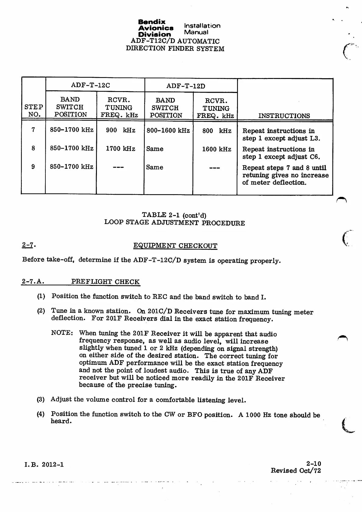
ADF-T-12C
ADF-T-12D
BAND
SWITCH
POSITION
RCVR.
TUNING
FREQ. kHz
BAND
SWITCH
POSITION
RCVR.
TUNING
FREQ. kHz
STEP
NO.
INSTRUCTIONS
7 850-1700 kHz
900 kHz 800-1600 kHz
800 kHz
R e p e a t i n s t r u c t i o n s i n
step 1except adjust L3.
R e p e a t i n s t r u c t i o n s i n
step 1except adjust C6.
R e p e a t s t e p s 7 a n d 8 u n t i l
retuning g i v e s n o in c r e a s e
o f m e t e r d e fl e c t i o n .
8 850-1700 kHz
1700 kHz Same
1600 kHz
850-1700 kHz9
Same
TABLE 2-1 (coni'd)
LOOP STAGE ADJUSTMENT PROCEDURE
(
2-7.
EQUIPMENT CHECKOUT
Before take-off, determine if the ADF-T-12C/D system is operating properly.
2-7.A.
PREFLIGHT CHECK
(1) Position the function switch to REC and the band switch to band I.
(2) Tune in aknown station. On 201C/D Receivers tune for maximum tuning meter
deflection. For 201F Receivers dial in the exact station frequency.
When tuning the 201F Receiver it wiH be apparent that audio
frequency response, as weU as audio level, will increase
slightly when tuned 1or 2kHz (depending on signal strength)
on either side of the desired station. The correct tuning for
optimum ADF performance will be the exact station frequency
and not the point of loudest audio. This is true of any ADF
receiver but will be noticed more readily in the 2OIF Receiver
because of the precise tuning.
(3) Adjust the volume control for acomfortable listening level.
(4) Position the function switch to the CW or BFO position. A1000 Hz tone should be
heard.
NOTE:
(
2-10
Revised Oct/72
I.B. 2012-1