Bandix
Avionics
Division
ADF-T12C/D AUTOMATIC
DIRECTION FINDING SYSTEM
Installation
Manual
SERVO AMPLIFIER/INDICATOR2-4. B.
Model 551A/C/E/RL indicators are designed for mounting behind the panel. Mounting-
ho le dim ens ions a re inc lude d on the out lin e d raw ings i n S ect ion III .
Install the servo amplifier/indicators using the appropriate outline drawing as aguide.
Carefully cut the dial opening in the panel and drill mounting holes. Allow at least three
inc h e s f o r c a b le c o nnect i o n s a n d r e m oval passa g e .
In dual installations, the two 551E indicators can be installed remotely using bracket
P/N 62C035. Check cable lengths between both 551E, the two receivers, the 551C
in d i c a to r a n d t h e 26 - vo l t 4 0 0 H z so u rc e . S ee fi g ur e 3 -2 .
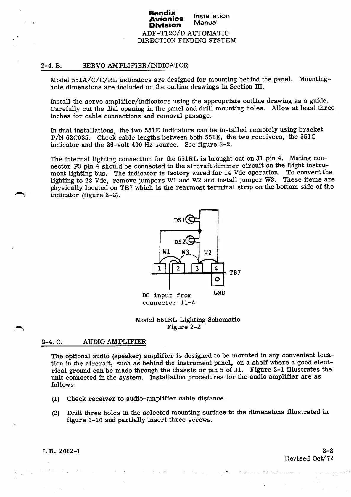
The internal lighting connection for the 551RL is brought out on J1 pin 4. Mating con¬
nector P3 pin 4should be connected to the aircraft dimmer circuit on the flight instru¬
ment lighting bus. The indicator is factory wired for 14 Vdc operation. To convert the
lighting to 28 Vdc, remove jumpers W1 and W2 and install jumper W3. These items are
physically located on TB7 which is the rearmost terminal strip on the bottom side of the
indicator (figure 2-2).
DSl
DS2©=
W1 Wi W2
X
2
3
TB7
O
GND
DC input from
c o n n e c t o r J l - 4
Model 551RL Lighting Schematic
Figure 2-2
AUDIO AMPLIFIER2-4. C.
The optional audio (speaker) amplifier is designed to be mounted in any convenient loca¬
tion in the aircraft, such as behind the instrument panel, on ashelf where agood elect¬
rical ground can be made through the chassis or pin 5of Jl. Figure 3-1 illustrates the
unit connected in the system. Installation procedures for the audio amplifier are as
follows:
(1) Check receiver to audio-amplifier cable distance.
(2) Drill three holes in the selected mounting surface to the dimensions illustrated in
figure 3-10 and partially insert three screws.
2-3
I.B. 2012-1
Revised Oct/72