Bendix
Avionics
Division
ADF-T12C/D AUTOMATIC
DIRECTION FINDER SYSTEM
Installation
Manual
2-6. A.
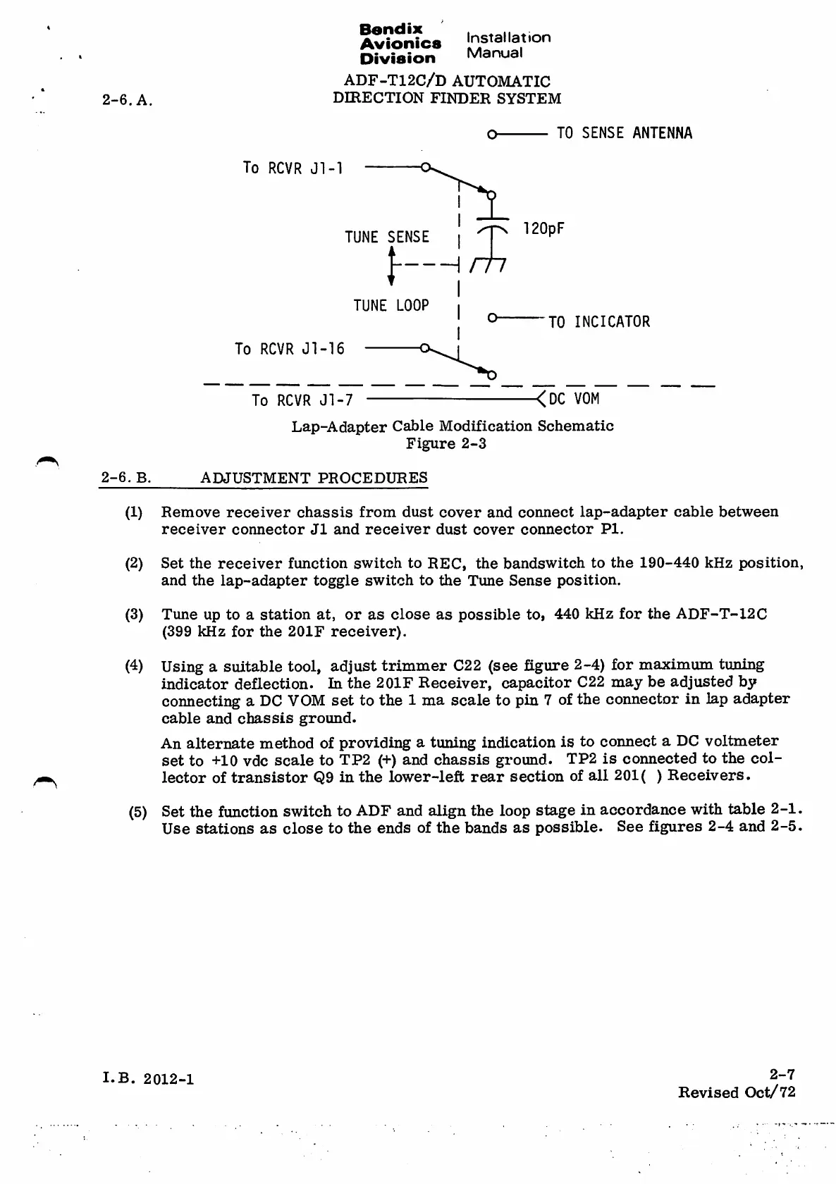
TO SENSE ANTENNA
o
To RCVR Jl-1
120pF
TUNE SENSE
m
TUNE LOOP
a
-TO INO ICATO R
To RC VR J l- 16
<DC VOM
Lap-Adapter Cable Modification Schematic
Figure 2-3
To RC VR J l- 7
2-6. B.
ADJUSTMENT PROCEDURES
Re m o v e r e ce i v e r c h a s s i s fr o m d u st c o v e r an d co n ne c t la p -a d a p t e r ca b l e b e tw e e n
r e c e i v e r c o n n e c t o r J 1 a n d r e c e i v e r d u s t c o v e r c o n n e c t o r P I .
(1)
Set the receiver function switch to REC, the bandswitch to the 190-440 kHz position,
and the lap-adapter toggle switch to the Tune Sense position.
Tune up to astation at, or as close as possible to, 440 kHz for the ADF-T-12C
(399 kHz for the 201F receiver).
Using asuitable tool, adjust trimmer C22 (see figure 2-4) for maximum tuning
indicator deflection. In the 2OIF Receiver, capacitor C22 may be adjusted by
connecting aDC VOM set to the 1ma scale to pin 7of the connector in lap adapter
cable and chassis ground.
An alternate method of providing atuning indication is to connect aDC voltmeter
set to +10 vdc scale to TP2 (+) and chassis ground. TP2 is connected to the col¬
lector of transistor Q9 in the lower-left rear section of all 201 ()Receivers.
Set the function switch to ADF and align the loop stage in accordance with table 2-1.
Use stations as close to the ends of the bands as possible. See figures 2-4 and 2-5.
(2)
(3)
(4)
(5)
2-7
I.B. 2012-1
Revised Oct/72