M A I N T E N A N C E P R A C T I C E S
1. GENERAL
A. This section of the manual contains information and procedures for performing tests and adjustments
together with corrective and preventative maintenance of the ADF-T-12B, CSystem.
2. ADJUSTMENT/TESTS
A. JOB/USE
The alignment procedures detailed in this section of the manual are performed to adjust the
system for optimum performance. The performance tests detailed in the following paragraphs
will determine whether the system meets its minimum performance requirements.
(1)
NOTE
Perform all alignment procedures in the order listed.
B. TEST EQUIPMENT REQUIRED
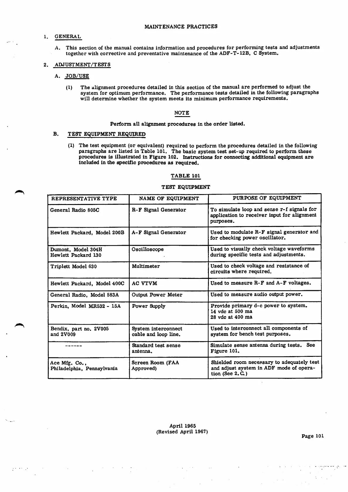
(1) The test equipment (or equivalent) required to perform the procedures detailed in the following
paragraphs are listed in Table 101. The basic system test set-up required to perform these
procedures is illustrated in Figure 102. Instructions for connecting ^ditional equipment are
included in the specific procedures as required.
T A B L E 1 0 1
TEST EQUIPMENT
P U R P O S E O F E Q U I P M E N TN A M E O F E Q U I P M E N T
R E P R E S E N T A T I V E T Y P E
To simulate loop and sense r-f signals for
application to receiver input for alignment
purposes.
R-F Signal Generator
General Radio 805C
Used to modulate R-F signal generator and
f o r c h e c k i n g p o w e r o s c i l l a t o r .
Hewlett Packard, Model 200B A-F Signal Generator
Used to visually check voltage waveforms
during specific tests and adjustments.
OscilloscopeDumont, Model 304H
Hewlett Packard 130
Used to check voltage and resistance of
c i r c u i t s w h e r e r e q u i r e d .
Triplett Model 630
Multimeter
Used to measure R-F and A-F voltages.
Hewlett Packard, Model 400C
AC VTVM
Used to measure audio output power.
General Radio, Model 583A O u t p u t P o w e r M e t e r
P r o v i d e p r i m a r y d - c p o w e r t o s y s t e m .
1 4 v d c a t 5 0 0 m a
2 8 v d c a t 4 0 0 m a
Perkin, Model MR532 -15A Power Supply
U s e d t o i n t e r c o n n e c t a l l c o m p o n e n t s o f
system for bench test purposes.
Bendix, part no. 2V005
and 2V009
System interconnect
cable and loop line.
Simulate sense antenna during tests. See
Figure 101.
Standard test sense
antenna.
Shielded room necessary to adequately test
and a d j u st s y s t e m in ADF m o d e of o p e r a¬
tion (See 2. C.)
S c r e e n R o o m ( F A A
Approved)
Ace Mfg. Co.,
Philadelphia, Pennsylvania
April 1965
(Revised April 1967)
Page 101