DESCRIPTION AND OPERATION
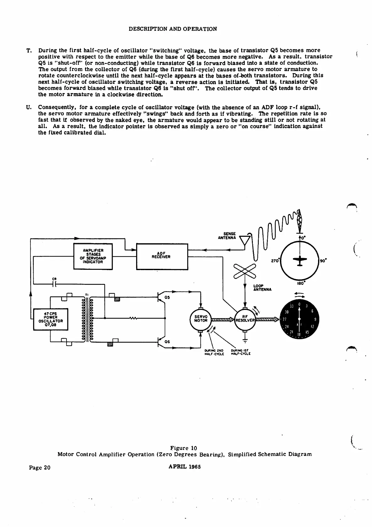
T. During the first half-cycle of oscillator "switching" voltage, the base of transistor Q5 becomes more
positive with respect to the emitter while the base of Q6 becomes more negative. As aresult, transistor
Q5 is "shut-off (or non-conducting) while transistor Q6 is forward biased into astate of conduction.
The output from the collector of Q6 (during the first half-cycle) causes the servo motor armature to
rotate counterclockwise until the next half-cycle appears at the bases of-both transistors. During this
next half-cycle of oscillator switching voltage, areverse action is initiated. That is, transistor Q5
becomes forward biased while transistor Q6 is "shut off. The collector output of Q5 tends to drive
t h e m o t o r a r m a t u r e i n a c l o c k w i s e d i r e c t i o n .
U. Consequently, for acomplete cycle of oscillator voltage (with the absence of an ADF loop r-f signal),
the servo motor armature effectively "swings" back and forth as if vibrating. The repetition rate is so
fast that if observed by the naked eye, the armature would appear to be standing still or not rotating at
all. As aresult, the indicator pointer is observed as simply azero or "on course" indication against
the fixed calibrated dial.
SENSE
ANTENNA
AMPLIFIER
STAGES
OF SERVOAMP
INDICATOR
AOF
RECEIVER
ca
LOOP
ANTENNA
Tl
05
TJ o o
o
o
o
o
o
47 CPS
POWER
OSCILLATOR
07.08
o o
SERVO
MOTOR
RF
■ wvo
w t M t / i i i T l - 2 1
RESOLVER
o o
o
o
o o
o
o o
o o
o to
06
tJ
CXJRING 1ST
malf-cycle
OJfliNG 2ND
half CYCLE
Figure 10
Motor Control Amplifier Operation (Zero Degrees Bearing), Simplified Schematic Diagram
APRIL 1965
Page 20