M A I N T E N A N C E P R A C T I C E S
C. SCREEN ROOM
t
(1) All tests performed on the system in the ADF mode of operation must be performed in ascreen or
shielded room so as to accurately simulate the conditions under which the loop antenna and as¬
sociated circuits would operate in afree-space, radiated signal field. If ascreen room is not
available, the Transdyne Model G-1 ADF test unit or equivalent must be utilized for testing the
system.
D. STANDARD TEST ANTENNA
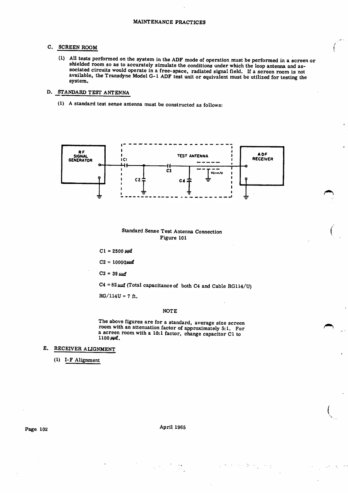
(1) Astandard test sense antenna must be constructed as follows:
RF
ADF
RECEIVER
TEST antenna
SIGNAL
generator
Cl
Hh
CJ
RGM4/U
C2 ±
C4 ir
Standard Sense Test Antenna Connection
Figure 101
Cl =2500 MMf
C2 =lOOOQWif
C3 =39 aid
C4 =S2uuf (Total capacitance of both C4 and Cable RG114/U)
RG/114U =7ft.
NOTE
The above figures are for astandard, average size screen
room with an attenuation factor of approximately 5:1.
ascreen room with a10:1 factor, change caoacitor Cl to
1100 Wif.
For
E. RECEIVER ALIGNMENT
(1) I-F Alignment
(
April 1965
Page 102