Bendix
Avionics
Division
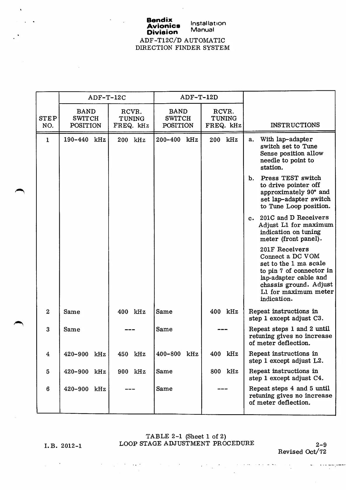
ADF-T12C/D AUTOMATIC
DIRECTION FINDER SYSTEM
Installation
Manual
ADF-T-12D
ADF-T-12C
BAND
SWITCH
POSITION
BAND
SWITCH
POSITION
RCVR.
TUNING
FREQ. kHz
RCVR.
TUNING
FREQ. kHz
STEP
INSTRUCTIONSNO.
With lap-adapter
switch set to Tune
Sense position allow
needle to point to
station.
P r e s s T E S T s w i t c h
t o d r i v e po i n t e r off
approximately 90° and
set lap-adapter switch
to Tune Loop position.
201C and DReceivers
A d j u s t L I f o r m a x i m u m
indication on tuning
meter (front panel).
201F Receivers
Connect aDC VOM
set to the 1ma scale
to pin 7of connector in
lap-adapter cable and
chassis ground. Adjust
L I f o r m a x i m u m m e t e r
indication.
190-440 kHz 200-400 kHz 200 kHz200 kHz1
a.
b.
c.
400 kHz
R e p e a t i n s t r u c t i o n s i n
step 1except adjust C3.
Repeat steps 1and 2until
re t u n in g g i v e s no in c re a s e
o f m e t e r d e fl e c t i o n .
R e p e a t in s t r u c t i o n s i n
step 1except adjust L2.
R e p e a t i n s t r u c t i o n s i n
step 1except adjust C4.
R e p e a t s t e p s 4 a n d 5 u n t i l
re t u n in g g i v e s no in c re a s e
o f m e t e r d e fl e c t i o n .
Same 400 kHz Same2
Same Same3
400 kHz450 kHz 400-800 kHz4 420-900 kHz
800 kHz
900 kHz
Same
5 420-900 kHz
420-900 kHz Same6
TABLE 2-1 (Sheet 1of 2)
L O O P S T A G E A D J U S T M E N T P R O C E D U R E
2-9
LB. 2012-1
Revised Oct/72