M A I N T E N A N C E P R A C T I C E S
the typical voltages to be found on the A+ line of the receiver and indicator circuits would be in
t h e a r e a o f 7 . 5 t o 1 0 v o l t s d - c .
The voltages across the leads of typical ohmmeters, are in many cases equal to the operating
potentials of transistors. Therefore, connecting an ohmmeter across atransistorized circuit
might cause the transistor to conduct, or become forward-biased from apreviously reverse-
b i a s e d s t a t e . T h i s w i l l r e s u l t i n e r r o n e o u s i n d i c a t i o n s o f t h e o h m m e t e r. I n s o m e c a s e s , t h e
meter potentials may be sufficiently high to damage the transistor. Transistors should always
be removed from the circuit before taking resistance measurements. In cases where the tran¬
sistors are soldered into the circuit board and cannot be easily removed, resistance measure¬
m e n t s s h o u l d n o t b e p e r f o r m e d .
T r a n s i s t o r C h e c k i n g
Transistor failure is seldom encountered under normal operating conditions. The few cases of
failure are due to excessive voltage or heat. Once atransistor has been damaged it will generally
be completely inoperative. In some cases, damage will be evidenced by increases noise. The
best way to check atransistor is to replace it with one known to be good. Atransistor checker
may also be used where marginal performance is suspected.
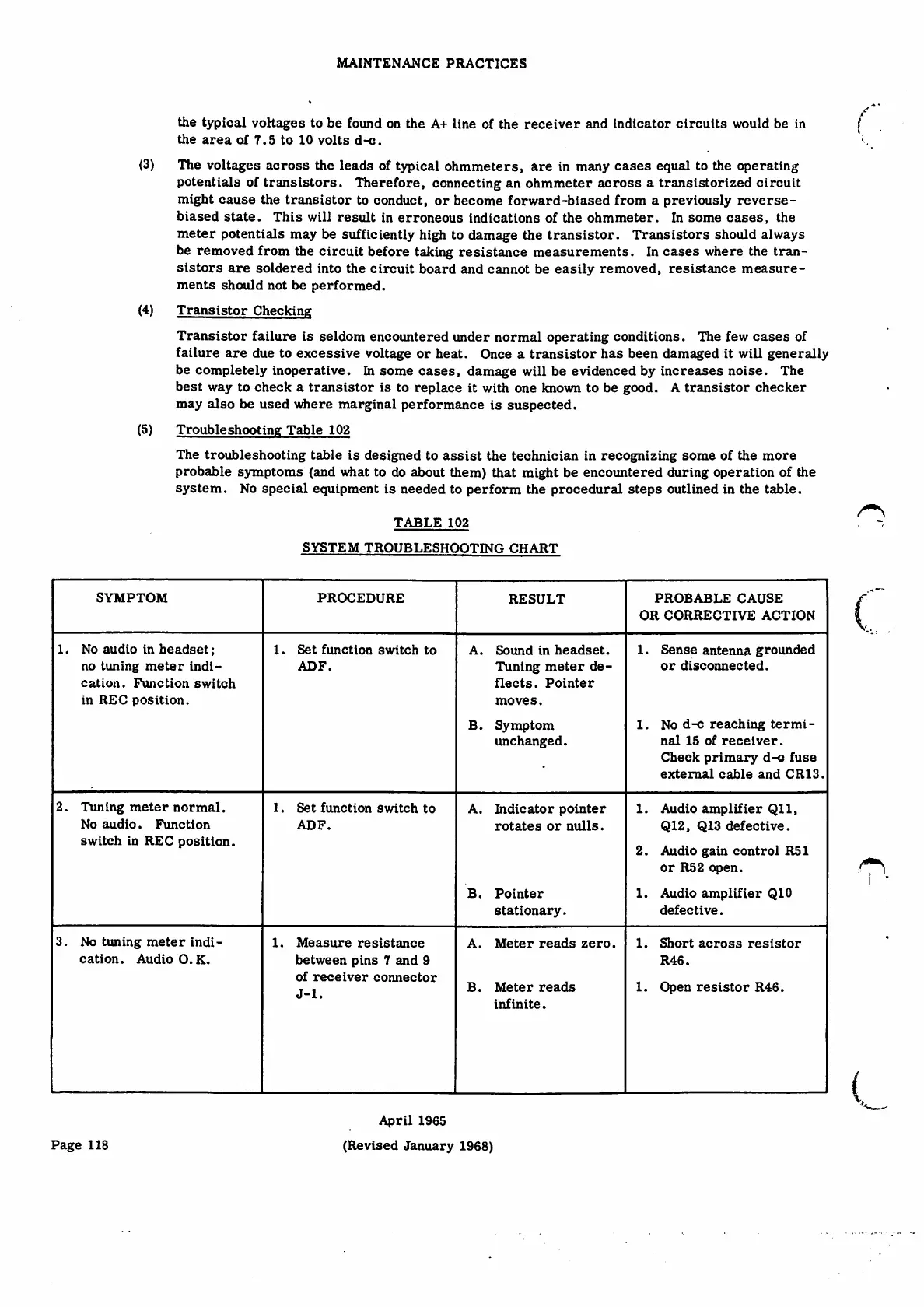
Troubleshooting Table 102
The troubleshooting table is designed to assist the technician in recognizing some of the more
probable symptoms (and what to do about them) that might be encoimtered during operation of the
system. No special equipment is needed to perform the procedural steps outlined in the table.
(3)
(4)
(5)
T A B L E 1 0 2
S Y S T E M T R O U B L E S H O O T I N G C H A R T
SYMPTOM
PROCEDURE P R O B A B L E C A U S E
O R C O R R E C T I V E A C T I O N
RESULT
(,
1. No audio in headset;
n o t u n i n g m e t e r i n d i ¬
cation. Function switch
in REC position.
1. Set function switch to
ADF.
Sound in headset.
Tu n i n g m e t e r d e ¬
flects. Pointer
moves.
1.
Sense antenna grounded
o r d i s c o n n e c t e d .
A.
N o d - c r e a c h i n g t e r m i ¬
nal 15 of receiver.
C h e c k p r i m a r y d - c f u s e
external cable and CR13.
B.
Symptom
unchanged.
1.
2 . T u n i n g m e t e r n o r m a l .
No audio. Function
switch in REC position.
1. Set function switch to
ADF.
1. Aud io am pl ifie r Qll ,
Q12, Q13 defective.
2. Audio gain control R51
or R52 ope n.
1 . A u d i o a m p l i fi e r Q I O
defective.
A . I n d i c a t o r p o i n t e r
r o t a t e s o r n u l l s .
B. Pointer
stationary.
3 . N o t u n i n g m e t e r i n d i ¬
cation. Audio O.K.
1. Measure resistance
between pins 7and 9
o f r e c e i v e r c o n n e c t o r
J-1.
S h o r t a c r o s s r e s i s t o r
R46.
A. M e t e r r e a d s z e r o . 1.
M e t e r r e a d s
infinite.
1.
O p e n r e s i s t o r R 4 6 .
B.
i
I
April 1965
(Revised January 1968)
Page 118