5
6. Never exceed manufacturer’s recommended
pressures.
7. Never connect or disconnect a hose or line
containing pressure; it may whip. Never remove a
component or plug unless you are certain all
system pressure has been depleted.
8. Use only genuine Bendix
®
replacement parts,
components and kits. Replacement hardware,
tubing, hose, fittings, etc. must be of equivalent
size, type and strength as original equipment and
be designed specifically for such applications and
systems.
9. Components with stripped threads or damaged
parts should be replaced rather than repaired. Do
not attempt repairs requiring machining or welding
unless specifically stated and approved by the
vehicle and component manufacturer.
10. Prior to returning the vehicle to service, make
certain all components and systems are restored to
their proper operating condition.
VALVE REMOVAL
1. Park the vehicle on a level surface and block the wheels
and/or hold the vehicle by means other than the air
brakes.
2. Drain the air pressure from all vehicle reservoirs.
3. Identify, mark or label all air lines and wiring cables and
their respective connections on the valve or antilock
controller to facilitate ease of installation.
4. Disconnect all air lines and wiring.
5. Remove the valve and controller assembly from the
vehicle.
VALVE INSTALLATION
1. Install all air line fittings and plugs making certain thread
sealing material does not enter the valve.
2. Install the assembled valve on the vehicle.
3. Reconnect all air lines and wiring cables to the valve and
controller assembly using the identification made during
VALVE REMOVAL step 3.
4. After installing the valve and controller assembly, test all
air fittings for excessive leakage and tighten as needed.
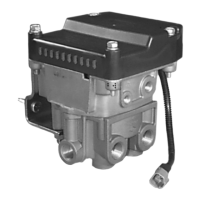
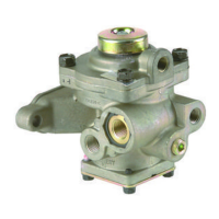
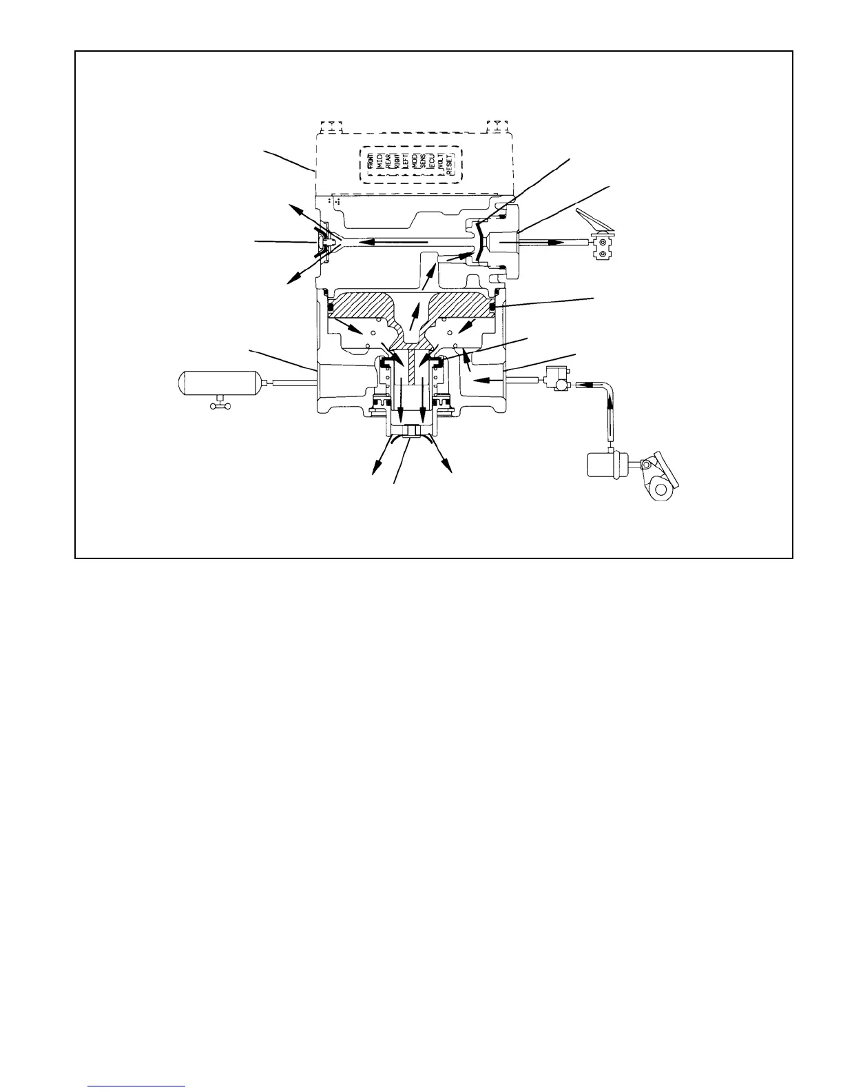
FIGURE 5 - AR-1
™
VALVE EXHAUST - BRAKE RELEASE
RESERVOIR
BRAKE
ACTUATOR
SUPPLY PORT
EXHAUST
ANTILOCK
CONTROLLER
QUICK EXHAUST DIA.
SERVICE PORT
RELAY PISTON
DELIVERY PORT
INLET/EXH. VALVE
ANTILOCK
MODULATOR
EXHAUST