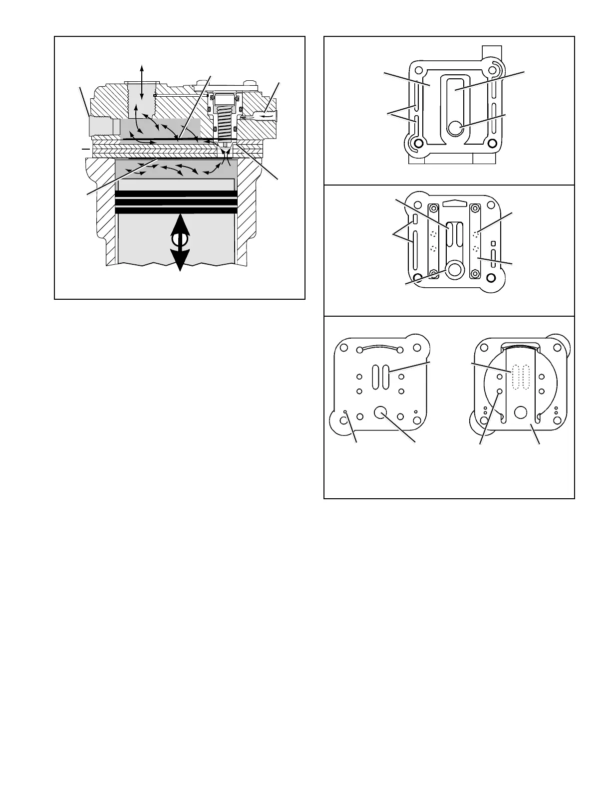
3
unloader piston is unseated a passage is opened between
the cylinder bore and the air inlet cavity in the cylinder head.
Air compression ceases. See figures 6 & 7.
As the piston moves from bottom dead center (BDC) to top
dead center (TDC) air in the cylinder bore flows past the
unseated unloader piston, into the cylinder head inlet cav-
ity and out the inlet port. On the piston down stroke (TDC
to BDC) air flows in the reverse direction, from the inlet
cavity past the unseated unloader piston and into the cylin-
der bore.
LUBRICATION
The vehicle's engine provides a continuous supply of oil to
the compressor. Oil is routed from the engine to the com-
pressor oil inlet. An oil passage in the crankshaft conducts
pressurized oil to precision sleeve main bearings and to
the connecting rod bearings. Spray lubrication of the cylin-
der bores, connecting rod wrist pin bushings, and ball type
main bearings is obtained as oil is forced out around the
crankshaft journals by engine oil pressure. Oil then falls to
the bottom of the compressor crankcase and is returned to
the engine through drain holes in the compressor mount-
ing flange.
COOLING
Cooling fins are part of the crankcase/cylinder block cast-
ing. Coolant flowing from the engine cooling system through
connecting lines enters the head and passes through inter-
nal passages in the cylinder head and valve plate assembly
and is returned to the engine. Proper cooling is important in
maintaining discharge air temperatures below the maximum
recommended 400 degrees Fahrenheit. Figure 8 illustrates
the various approved coolant flow connections. See the tabu-
lated technical data in the back of this manual for specific
requirements.
PREVENTATIVE MAINTENANCE
Important Note: Review the warranty policy before perform-
ing any intrusive maintenance procedures. An extended
warranty may be voided if intrusive maintenance is performed
during this period.
EVERY 6 MONTHS, 1800 OPERATING HOURS
OR AFTER EACH 50,000 MILES WHICHEVER OC-
CURS FIRST PERFORM THE FOLLOWING
INSPECTIONS AND TESTS.
FIGURE 7 - CYLINDER HEAD AND VALVE PLATE ASSY.
Cylinder Block Side of Valve Plate Assembly
Cylinder Head Side of Valve Plate Assembly
Air Inlet Slots
(2)
Valve Plate Assembly Side of Cylinder Head
Coolant
Transfer Slots
Air Inlet
Slots (2)
Discharge
Ports (4)
Unloader
Piston Bore
Inlet Reed
Valve/Gasket
Without Inlet Valve Inlet Reed Valve in Place
Alignment
Pin Holes
Discharge
Ports (4)
Unloader Piston
Seating Surface
Discharge
Valves (2)
Coolant
Transfer Slots
Air Inlet
Cavity
Discharge
Cavity
Unloader Piston
Bore
FIGURE 6 - OPERATIONAL-UNLOADED
AIR INLET
PORT
AIR
DISCHARGE
PORT
DISCHARGE
VALVE
CLOSED
VALVE
PLATE
PISTON MOVES
UP & DOWN
INLET
VALVE
CLOSED
UNLOADER
PISTON UP
&
UNSEATED
AIR FROM
GOVERNOR
UNLOADER
PORT