27
2.6 CLEARING DIAGNOSTIC
TROUBLE CODES (DTCS)
1. Connect a current version of the Bendix
®
ACom
®
PRO
™
Diagnostic Software to the vehicle.
2. Once the roll call is complete, you can view active and
inactive Diagnostic Trouble Codes (DTCs) and clear
DTCs from all vehicle components or solely from a
selected Bendix controller.
3. To read and clear DTCs from all vehicle components
at the same time, select the vehicle on the roll call and
clear the DTCs by selecting “Clear Faults.”
4. To read and clear DTCs from a specific Bendix
Electronic Control Unit (ECU), select the Bendix ECU
on the roll call and select “Clear Faults.”
For assistance with ACom PRO Diagnostic Software,
contact the Bendix Tech Team at 1-800-AIR-BRAKE
(1-800-247-2725, option 2, option 2).
2.7 TROUBLESHOOTING DIAGNOSTIC
TROUBLE CODES: POWER SUPPLY
IGNITION VOLTAGE TOO LOW
Measure the ignition voltage under load. Ensure that the
ignition voltage is greater than 10 VDC (Volts DC). Check
the vehicle battery and associated components. Inspect
for damaged wiring, damaged or corroded connectors,
and loose connections. Check the condition of the fuse.
IGNITION VOLTAGE TOO HIGH
Measure the ignition voltage. Ensure that ignition voltage
is not greater than 16 VDC. Check the vehicle battery
and associated components. Inspect for damaged wiring,
damaged or corroded connectors, and loose connections.
POWER SUPPLY TESTS
1. Take all measurements at the radar sensor harness
connector.
2. Place a load (i.e. 1157 stop lamp) across the supply
voltage and ground connection. Measure the voltage
with the load. The voltage on pin 1 to ground pin 8
should measure between 10 to 16 VDC.
3. Check for damaged wiring, damaged or corroded
connectors, and loose connections.
4. Check the condition of the vehicle battery and associ-
ated components. Ensure the connection to ground is
secure and tight.
5. Using the procedures described by the vehicle
manufacturer, check the alternator output for excessive
noise.
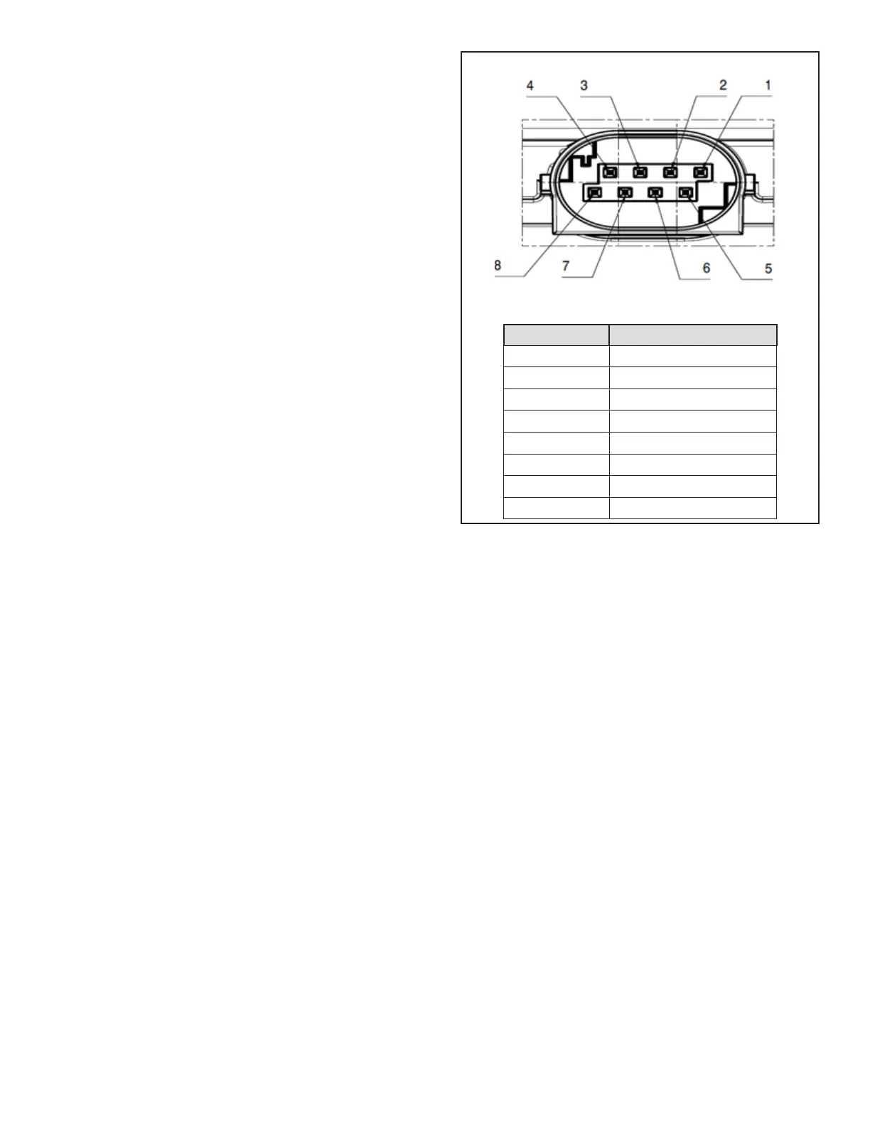
Table 5 – Harness Connector Pins
Power Supply Pin Codes (4.5)
(Looking into the Front of the Harness Connector)
Pin # Description
1 Ignition Voltage (+)
2 Not Used
3 Not Used
4 J1939 CAN LOW
5 Not Used
6 Not Used
7 J1939 CAN HIGH
8 Ground (-)
2.8 SERIAL DATA (J1939)
COMMUNICATIONS LINK
Check for a loss of communications between the Bendix
®
Fusion
™
FLR-25
™
Radar Sensor, the Antilock Braking
System (ABS) controller, the engine ECU, and other
devices connected to the J1939 link. Check for damaged
or reversed J1939 wiring. Check for corroded or damaged
connectors and loose connections. Using procedures
described by the vehicle manufacturer, verify the presence
of the engine ECU and the ABS controller on the J1939
link. This can be done using the roll call function the ACom
PRO Diagnostic Software.
Verify the engine ECU conguration. Check for other
devices inhibiting J1939 communications.
NOTE: The FLR-25 Radar Sensor will not report newly
active J1939 DTCs until the engine has been running for
15 seconds. Do not attempt to diagnose J1939 DTCs with
the engine running.