29
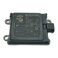
2.12 RESETTING THE RADAR
SERVICE ALIGNMENT
1. Connect a current version of Bendix
®
ACom
®
PRO
™
Diagnostic Software and select “Bi-Directional” from
the main menu. Select the Bendix radar sensor and
select "Radar Service Alignment."
2. Select "Start" to begin the radar service alignment
test. See Figure 7.
Figure 7 – Bendix
®
ACom
®
PRO™ Radar Service Alignment
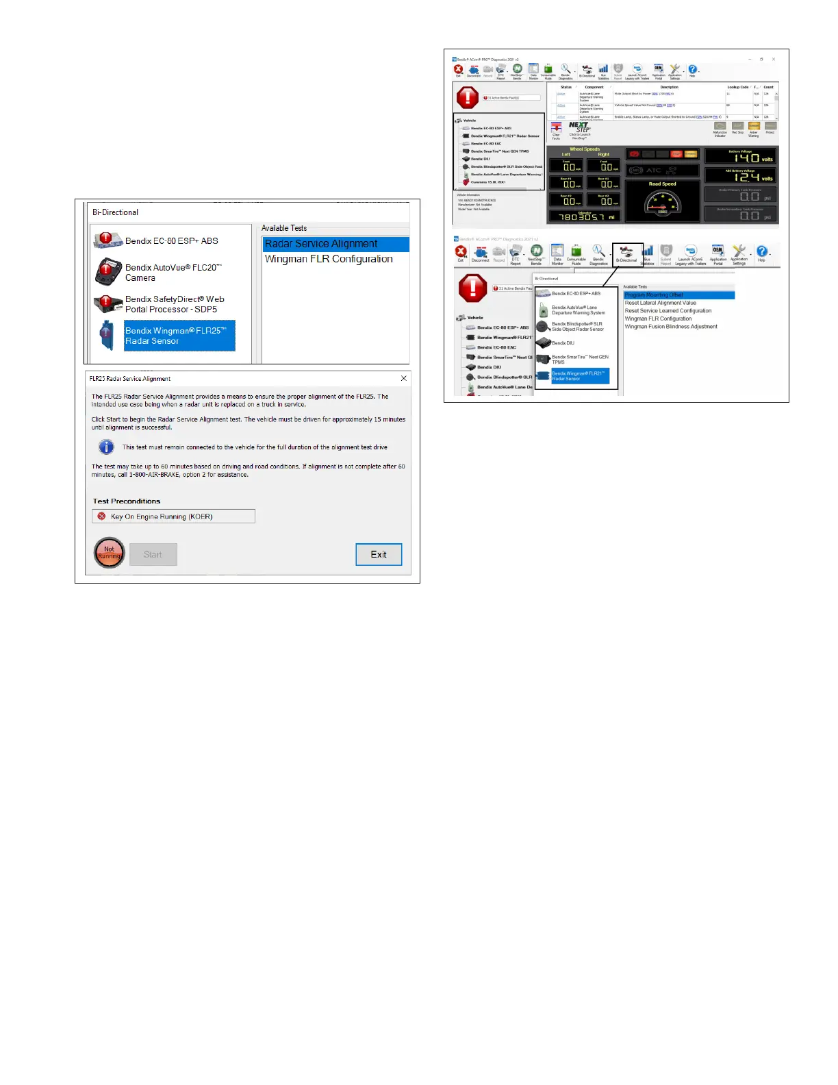
3.0 OTHER SYSTEM FEATURES
3.1 READING BENDIX
®
FUSION
™
SYSTEM KEY INDICATORS
1. Connect a current version of the ACom PRO
Diagnostic Software key system indicators from the
roll call. Key Electronic Control Unit (ECU) indicators
will be shown at the bottom left of the screen below
the roll call. Some information shown in this includes
the make, model, serial number, software version,
etc.
2. Additional ECU indicators can be found by selecting
“Bi-Directional” from the main menu. Select the Bendix
controller and the controller-specic conguration
option in the populated menu.
For assistance with the ACom PRO Diagnostic Software,
contact the Bendix Tech team at 1-800-AIR-BRAKE
(1-800-247-2725, option 2, option 2).
Figure 8 – Bendix
®
ACom
®
PRO™ Screen Showing the
Conguration Number
3.2 BENDIX FUSION SYSTEM
DIAGNOSTIC TROUBLE CODE
(DTC) SELF-CLEARING
1. Connect a current version of the ACom PRO
Diagnostic Software to the vehicle.
2. Once the roll call is complete, you can view active
and inactive DTCs and clear DTCs from all vehicle
components or solely from a selected Bendix
controller.
3. To read and clear DTCs from all vehicle components
at the same time, select the vehicle on the roll call and
clear the DTCs by selecting “Clear Faults.”
4. ToreadandclearDTCsfromaspecicBendixECU,
select the Bendix ECU on the roll call and select
“Clear Faults.”
3.3 FOLLOWING DISTANCE
ADJUSTMENT SWITCH (OPTIONAL)
If the vehicle is equipped with the following distance
adjustment switch and the following distance does not
change after an adjustment is made, the switch, wiring,
or a controller on the vehicle should be checked using
the diagnostic procedures described by the vehicle
manufacturer. The radar sensor receives the driver’s
desired following distance on the J1939 data communication
link from a controller on the vehicle. No DTC will be set
if the vehicle is not equipped with a following distance
adjustment switch. Refer to Table 6 for further information
on conguration settings.