32
Appendix A
Bendix
™
FLR-25
™
Radar Sensor Mounting Clearance
A.3 Bendix
™
FLR-25
™
Radar Sensor
Mounting Clearance
CAUTION: Vehicle equipment, including bumpers,
deer guards, etc. should not infringe upon the zone
used by the radar sensor shown in Figure 1 to emit
and receive radar waves. Failure to comply with this
requirement may impair the function of the collision
mitigation system. Bendix recommends to only use
OEM-approved and supplied radar covers with our
radar products. OEM-supplied radar covers have been
tested and approved for radar operation with minimum
degradation or attenuation of the radar signal. Non-
approved radar covers may lead to degradation of the
driver assistance system. To qualify a new radar cover
design, please contact the vehicle OEM.
NOTE: Bendix does not certify nor oer warranty on
Bendix
®
Fusion systems where system performance is
aectedbyobstructionsofanykind.Furthermore,Bendix
will not certify or approve of any third-party bumper
guards mounted on the front of the vehicle. Bendix does
NOT recommend the removal of an Advanced Driver
Assistance System (ADAS) from a vehicle. This document
gives general guidelines that will work for most vehicles;
exceptions may exist.
For proper operation of the FLR-25 Radar Sensor, adhere
to the following guidelines:
• The radar sensor assembly should be OEM-installed
onthevehiclefollowingallOEMspecications.
• Theradar’seldofviewmustNOThaveinterference
from any other vehicle components such as bumpers,
cow-catcher bumpers, engine blankets, seasonal
decorations, or any other commonly mounted front-
of-vehicle components. The radar signal is emitted
from the front of the sensor with a spreading beam.
The approved OEM-provided radar cover is the only
item that is to be placed in front of the radar. In order
to ensure that no adverse interference is experienced
from bumpers or other nearby vehicle equipment, a
suitable clearance must be maintained around the
radar. This clearance must be maintained regardless if
the vehicle is stationary or in motion. See the diagram
below for a general guide and an example of how to
calculate the zone required. The front of the radar may
not be accessible to measure from; it may be behind
the OEM radar cover.
Forward deer/moose guards: The eld of view of both the radar and the camera need to be kept clear of any
obstruction or the Fusion system performance may be aected. Bendix does not recommend the use of any
forward vehicle guards that may interfere with a sensor’s eld of view, and use of such guards may void any
Bendix warranty. Bendix includes the radar eld of view diagram in the Service Data Sheet as a reference to
help assist those eets who are considering placement of such forward vehicle guards. Also, do not move
the radar as it is designed by Bendix and the OEM to operate in the location placed by the OEM during factory
installation.
Appendix A
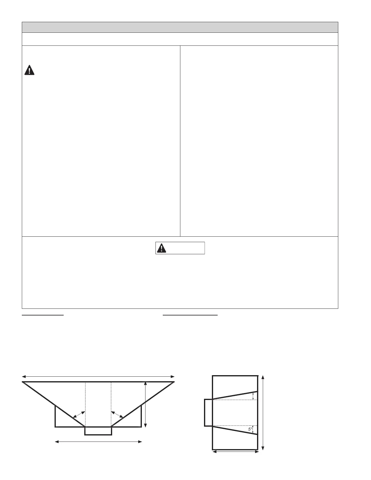
Measure from the raised surface at
the front of the radar.
For proper sensor performance,
the areas in front of and around the
sensor antenna radiation cone need
to be kept free of any materials or
objects that may disturb the radar
function.
The only exceptions are
OEM-approved covers.
NOTE: Drawings are representative only and not to scale. Dimensions are accurate.
IMPORTANT
KEEP-OUT ZONE
Length: 98 in. (250 cm)
Height: 15 in. (38 cm)
Width (distance from radar midpoint): 20 in. (50 cm)
This area needs to be kept free of any materials or
objects that may disturb the radar function. For example,
metallic parts shall not violate this Keep-out Zone.
Azimuth: 67° | Elevation: 15°
VERIFICATION ZONES
Length: 40 in. (102 cm)
Height (on both the top and bottom of the Keep-out Zone): 12.5 in. (31.75 cm)
Width (distance from radar midpoint): 20 in. (50 cm)
Any objects present in these areas (on both the top and bottom of
the Keep-out Zone) should be veried by the manufacturer of the
intruding object not to cause degradation of system performance.
Failure to do so can result in impaired functions of the system
and can result in false-positive activation of the system or a
collision causing property damage, serious injuries, or death.
FLR-25
98 in. (250 cm)
40 in. (102 cm)
20 in. (50 cm)
67° 67°
KEEP-OUT ZONE
VERIFICATION
ZONE
VERIFICATION
ZONE
TOP VIEW
FLR-25
40 in. (102 cm)
20 in. (50 cm)
15°
KEEP-OUT ZONE
VERIFICATION
ZONE
VERIFICATION
ZONE
SIDE
VIEW
15°