Autostacker™ Parking Lift 30 P/N 5900002 — Rev. D — August 2019
Working with Return Lines and Compression Fittings
Autostacker uses Return Lines made of a roll of ¼ inch, polyethylene Tubing (also called Poly-Flo®)
that is used with Compression Fittings to attach to the Air Cylinders and the Return Line Connectors.
The components involved with Compression Fittings include:
• ¼ inch, black, polyethylene Tubing. The Return Lines require several lengths of tubing to
make the necessary connections back to the Console.
• Elbow Compression Fittings (also called a 90° fitting). The Return Lines use Elbow Fittings to
attach to each Hydraulic Cylinder and one that connects to the Console.
• Tee Compression Fitting. The two Return Lines hooked up to the Hydraulic Cylinders connect
to a Tee Compression Fitting that goes back to the Power Unit.
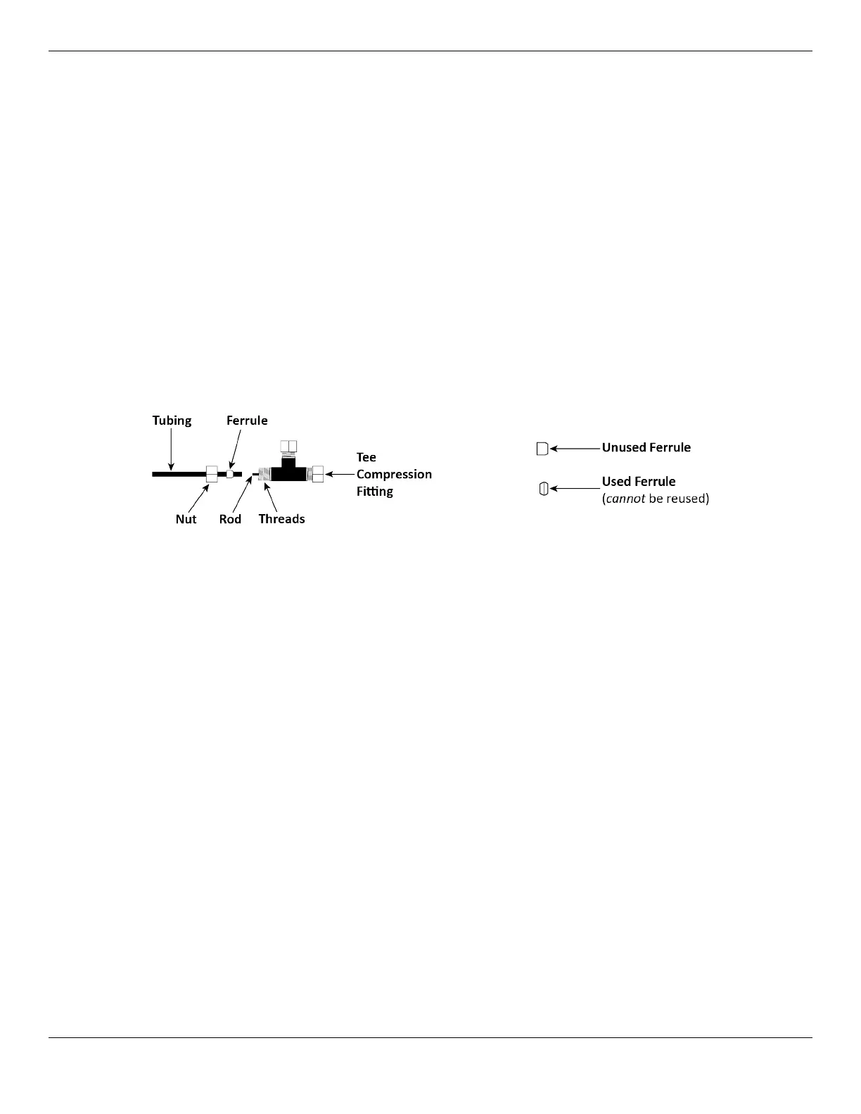
• Nuts, Ferrules, Rods, and Threads. Each connector on Elbow and Tee Compression
Fittings have a Nut, Ferrule, Rod, and Threads. The Nut holds the tubing and Fitting together. The
Ferrule compresses when you tighten the Nut on the Threads to make a secure connection. The
Rod goes inside the Tubing so that there are no leaks.
The following drawing shows the components of a connector on a Tee Compression Fitting
Important:
Ferrules can only be tightened once
. When you tighten the Nuts on the
Threads, the Ferrules get compressed; it changes shapes and
cannot
be used
again.
To connect the Return Lines:
1. Attach a 90° Fitting (Elbow Fitting -04 COMP x -06 NPT) to one of the two Return Line connectors
on the Power Unit.
There are two Hydraulic Return connectors on the Power Unit, one on each side; they work the
same, so choose the one that is best for you.
You only need to use one, not both
. They are
shown in the drawing in Connect the Power Unit.
2. Attach a 90° Fitting (Elbow Fitting -04 COMP x -04 NPT) to both Return Line Connectors near the
top of each Hydraulic Cylinder.
3. Locate a T Connector and put it near the bottom of the Hydraulic Cylinder closest to the Console.
4. Locate the Return Line tubing.
5. Cut a piece of tubing of appropriate length for each of the three Return Line segments.
6. Connect a Return Line between the Power Unit and the T Connector.
7. Connect a Return Line between the T Connector and the Return Line connector on the Hydraulic
Cylinder nearest the Console.
8. Connect the final Return Line to the T Connector, route it through the Bottom Connector Tube,
then connect it to the Return Line connector on the Hydraulic Cylinder furthest from the Console.