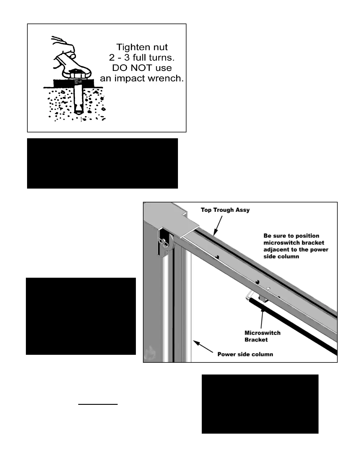
6. With the shims and anchor bolts in place,
tighten by securing the nut to the base then
turning 2 - 3 full turns clockwise. DO NOT use an
impact wrench for this procedure. ( See Fig. 8 )
STEP FIVE
( Mounting The OFFSIDE column. )
1. Position the OFFSIDE column at the desig-
nated chalk locations and secure to the floor fol-
lowing the same procedures as outlined in
STEP FOUR
Fig 8
NOTE:
To ease installation of the top beam, it helps to
keep the anchor bolts loose on one of the
columns until the top beam is mounted.
STEP SIX
( Mounting the OVERHEAD BEAM. )
1. Remove all of the Equalizer pulleys
in preperation of installing the Top
Trough assy.
Fig 9
Important Note
YOU MUST POSITION THE
SWITCH ENCLOSURE ADJACENT
POWERSIDE COLUMN.
2. Using a lifting devise, raise the OVERHEAD
beam into position on top of the columns. Bolt to
the columns using the 10 mm Hex Bolts, Nuts
and Washers. YOU MUST
POSITION THE
SWITCH ENCLOSURE ADJACENT POWER-
SIDE COLUMN. (Fig 9)
NOTE:
In order to route the
equalizer cables the
pulleys must be
removed