12
STEP 4
(Aligning the Ramp Assemblies)
1. Lift the Left Ramp Assembly and Right Ramp assem-
bly into position and set the ramps down on to the layout
created in Step 3
2. Align the Sliding Pivot Baseplates with the chalklines
that were drawn in Step 3. (See Fig 4.1)
3. Align the Fixed Pivot Baseplates with the chalklines
that were drawn in Step 3, using care so that the Sliding
Pivot Baseplates do not shift during alignment. (See Fig
4.2)
4. DO NOT attempt to bolt down the ramp assemblies at
this time.
STEP 5
(Power Unit Console Installation)
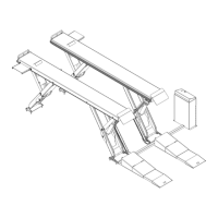
1. Place the Power Unit Console next to the Right
Ramp Assembly’s Sliding Pivot Baseplate and align it
using the measurements as shown in Figure 5.1
2. Using the console’s baseplate as a guide drill two 3/8”
holes into the concrete oor 1-1/2” deep making sure not
to let the drill wobble. DO NOT ream the holes after drill-
ing. (See Fig 5.2)
Fig 4.2
Fig 4.1
425mm
16 3/4"
905mm
35 3/4"
Approach
Fig 5.1
Fig 5.2
 Loading...