Bennett T75 Operation, Service, & Parts Manual Operation
15
THEORY OF OPERATION
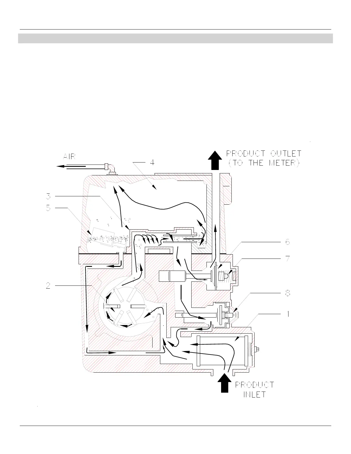
See Figure 10 for numbers in parenthesis.
The product is drawn from the underground storage tank through the strainer screen of Filter (1).
The Rotary Vane Pumping Unit (2) pressurizes the fluid.
Product enters the centrifugal Air Separator Assembly (3). Any air present is forced out the air tube along with a small amount of liquid
into the Atmospheric Chamber (4).
Product collected in the atmospheric chamber is returned to the pump intake across the non-return float when the liquid level in the
chamber lifts the float and valve assembly from its Seat (5). Any air is then vented to the atmosphere through the vent tube.
Air free product leaving the air separator opens the Control Valve (6) and is pumped to the meter. The control valve includes a built-in
Relief Valve (7) which relieves excess pressure caused by hot weather expansion.
Product passes through the meter where it is accurately measured, then through the hose and nozzle into the vehicle being fueled.
Whenever the nozzle is not fully opened, some liquid is relieved into the pump intake through the Bypass Valve (8).