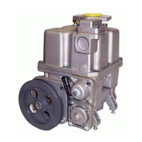
The Bennett T-75 Hydraulic Pumping Unit is a rotary vane type pump designed for flammable liquids, primarily used in fuel dispensing systems. This manual, dated October 26, 2018 (Rev G), provides comprehensive information on its operation, service, and parts.
Function Description:
The T-75 pumping unit is a positive displacement, sliding vane pump that pressurizes fluid drawn from an underground storage tank through a strainer screen. It features an integrated air eliminator that uses a vortex effect to separate air and foam from the liquid, venting the air to the atmosphere while returning recovered liquid to the pump intake. A bypass valve limits the maximum working pressure, and a control valve assembly ensures downstream hydraulic components are filled with liquid and includes a relief valve to handle excess pressure from thermal expansion. The unit is designed for efficient and low power consumption, making it suitable for both standard and high displacement flow rate applications.
Important Technical Specifications:
U.S. Specifications:
- Power Requirements @ Maximum Flow & Pressure: 22 gpm (80 lpm) at 700 RPM with 3/4 HP Motor (0.55kW)
- Maximum Flow Rate: 24 gpm / 90 lpm
- Noise Level: 72 dB
- Maximum Operating Pressure: 50 psi
- Maximum Motor Power Requirements: 1200 watts / 1.2 kW
- Bypass Pressure: Adjustable
- Minimum Dry Suction: 8 in HG
- Minimum Wet Suction: 21 in HG
- Micron Filter (μ): N/A (though various micron filters are available as parts)
- Air Elimination: According to OIML, CEE 77.313 Regulation
- Weight: 36 lbs. (79kg)
European Specifications:
- Power Requirements @ Maximum Flow & Pressure: 22 gpm (80 lpm) at 700 RPM with 1 HP Motor (0.75kW)
- Maximum Flow Rate: 80 L/min
- Noise Level: 72 dB
- Maximum Operating Pressure: 3.5 bar
- Minimum Pressure: 0.7 bar
- Maximum Motor Power Requirements: 1200 watts / 1.2 kW
- Bypass Pressure: Adjustable
- Minimum Dry Suction: 400 mb
- Minimum Wet Suction: 700 mb
- Micron Filter (μ): 10, 35, 70 according to conditions of use
Dimensions:
- Flanged Outlet Style (Vertical): 12 39/64" (320 mm)
- Tubular Outlet Style (Vertical): 11 5/8" (295 mm)
- Flanged and Tabular Outlet Style (Horizontal): 8-3/4" x 11-15/16" (222 x 303 mm)
- Flanged and Tabular Outlet Style (Depth): 11.15/16" (222 x 303 mm)
Usage Features:
The T-75 pumping unit is compatible with the SB-100 Meter and is available in two main models:
- Type 75D: For standard fuels and Gasoline/Ethanol blends with nominal ethanol concentrations up to 15%.
- Type 75A: For use with Gasoline/Ethanol blends with nominal ethanol concentrations up to 85%.
It features self-lubricating bearings to prevent seizure when the tank is pumped dry and threaded test connections for field diagnostics. The internal outlet control valve minimizes pressure surges, and an integral filtration system allows for selection of micron ranges. A drain plug facilitates servicing and filter replacement. The unit offers flanged outlets for direct meter mounting or tubular outlets for remote meter mounting, and can have either a flanged bottom inlet (vertically aligned 1-1/2" NPT) or a 4-bolt filter cover side inlet. Patented internal design features are incorporated to reduce the possibility of vapor lock.
For installation, it is crucial to follow PEI/RP100 and PEI/RP200 recommended practices, as well as all local, state, and federal requirements. The air eliminator (copper) tube must remain open to the atmosphere for proper ventilation. To achieve maximum flow rates on a self-contained pump, the total horizontal piping length between the pump and tank should not exceed 60 feet, static lift on self-contained units should not exceed 10 feet, and new 1-1/2" or 2" galvanized or approved non-metallic pipe should be used depending on the GPM requirements. When installing units for high alcohol products (e.g., E100), plumbing must be confirmed to handle alternative fuels, and special piping materials or components may be required for E25, E85, and other ethanol blends.
Maintenance Features:
The manual emphasizes that only trained personnel should work on this equipment, and all service and maintenance must be performed by authorized personnel or Bennett certified technicians. Before any service, all electrical supplies must be shut off and secured, and all valves in incoming piping must be closed. The emergency shut-off valve (fire valve, shear valve, or impact valve) must also be closed.
Troubleshooting guidance is provided for common issues such as the pump not delivering fuel, slow delivery, inaccurate delivery, fuel running out of the vent tube, and the computer jumping when the pump is turned on. Solutions often involve cleaning or replacing components like the vent pipe, strainer screen, filter assembly, bypass valve, float valve, control valve, or checking for obstructions in the suction line. Regular inspection of the v-belt, motor voltage, and pump blades is also recommended. For parts ordering, a complete model and serial number, including the date code, is required, and rebuilt parts are identified with an "RB" prefix for warranty claims.