Bennett T75 Operation, Service, & Parts Manual Operation
13
SECTION 3: OPERATION
OPERATION
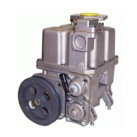
The following section describes each of the main components of the T75 pumping unit and the interface characteristics at each component. Refer
to the diagram on the next page for item locations. For any questions, please contact Bennett Technical Support at 1-800-423-6638.
The pump assembly has the following main components: (See Figure 9 for numbers in parenthesis.)
Body (1)
The inlet is designed to accept a triangular inlet flange with a 3-hole bolt pattern.
Cover (2)
The Flanged Outlet is used for direct meter mounting
The Tubular Outlet is used for remote meter mounting (as shown on page 6)
Filter (3) located in the horizontal position. Note: The filter cover includes a pipe plug to drain the pump.
An optional Inlet Check Valve (19) is available to hold product in the suction line when the pump is turned off. It maintains a vacuum
in the line preventing fuel from leaking through a loose joint into the ground.
Rotating Pump (4) with Radial Carbon Blades
The Throwout Rings (5) maintain contact of the blades to the stator.
The Stator (6) turns clockwise and is tightly fitted in the pump body.
The Rotor (7) is made of cast iron with a chrome-plated shaft.
The Self-Lubricated Bearings (21) are used to prevent seizure when tank is pumped dry.
The Cover (8), also of cast iron, encapsulates the rotor and the stator.
An Air Elimination Assembly (9), a patented fully static device, uses a vortex effect.
The insert (10) starts spinning the fluid.
The foam and the air pass through the Tube (11) and evacuated through the Orifice (12).
A Drain Line Eliminator (13) or atmospheric chamber of 1.2-gallon (4.5 liter) capacity.
The Float Valve Assembly (14) provides for the recovery of liquid from the chamber, while air is evacuated through the Vent Tube
(15).
A Non-Return Float (20) seals the atmospheric chamber when the pump is turned off to prevent flooding and spilling out onto the
driveway.
A Bypass Valve (16) is used to limit the maximum working pressure.
Its cover includes a device to adjust the bypass pressure (optional in USA)
A Control Valve Assembly (17) assures that all downstream hydraulic components are filled with liquid. This valve has a Relief Valve (18)
to relieve excess pressure.
NOTE: A diaphragm operated preset valve is available as an option.