Bennett T75 Operation, Service, & Parts Manual Product Introduction
6
EUROPEAN SPECIFICATIONS
Power Requirements @ Maximum Flow & Pressure ............................................................... 22 gpm (80 lpm) at 700 RPM with 1 HP Motor (0.75kW)
Maximum Flow Rate ............................................................................................................................................................................................ 80 L/min
Noise Level ................................................................................................................................................................................................................ 72 dB
Maximum Operating Pressure ................................................................................................................................................................................ 3.5 bar
Minimum Pressure .................................................................................................................................................................................................. 0.7 bar
Maximum Motor Power Requirements ............................................................................................................................................ 1200 watts / 1.2 kW
Bypass Pressure ................................................................................................................................................................................................ Adjustable
Minimum Dry Suction ............................................................................................................................................................................................ 400 mb
Minimum Wet Suction ........................................................................................................................................................................................... 700 mb
Micron Filter () ................................................................................................................................................ 10, 35, 70 according to conditions of use
Air Elimination ................................................................................................................................................According to OIML, CEE 77.313 Regulation
Pump Curve ............................................................................................................................................................................................. Refer to Figure 3
INSTALLATION PIPI NG FOR T YPE 75 PUMP DISPENSER
Refer to the PEI/RP100, Recommended Practices for Installation of Underground Liquid Storage Systems, PEI/RP200, Recommended Practices for
Installation of Aboveground Liquid Storage Systems, and all local, state, federal requirements, and accordance’s prior to any installation of all
equipment.
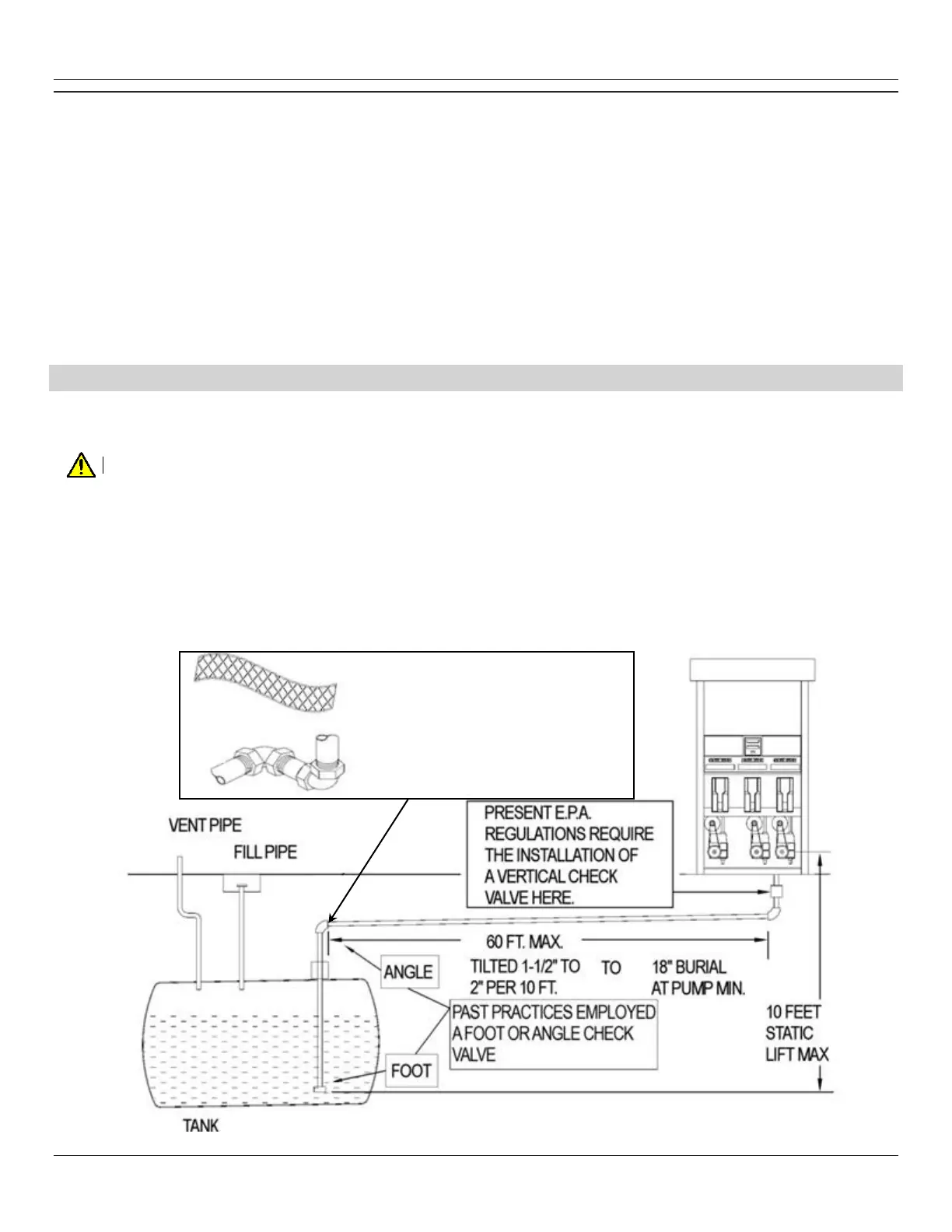
CAUTION: THE AIR ELIMINATOR (COPPER) TUBE MUST REMAIN OPEN TO THE ATMOSPHERE FOR PROPER VENTILATION.
To obtain maximum flow rates on a self-contained pump, follow these guidelines.
1. The total length of horizontal piping between the pump and tank must be no longer than 60 feet.
2. Static lift on self-contained units must not exceed 10 feet (vertical distance between product level in the storage tank and the center of
the pumping unit).
3. Use new 1-1/2” galvanized or approved non-metallic pipe for 10-15 GPM pumps. Use new 2” galvanized or approved non-metallic pipe
for 20-24 GPM pumps.