- 63 -
Feedback Circuit
1J.26051.041
PR827
D801
BAV70
A1
J
A2
R841
33K
C838
0.1U
C829
15P J
C830
15P J
R831
3M
R832
3M
F1
F3
D806
BAV70
A1
J
A2
TP801
TP802
TP804
TP803
R819
100K
R820
20K F
C820
470P J
C819
5PF D
C821-2
R821
100K
R822
20K F
C822
470P J
C821
5PF D
R810
1M F
C808
0.01U K
CN801
2K62272102
1
1
2
2
CN802
2K62272102
1
1
2
2
R815
2.2K
R827
365 F
R816
2.2K
C814
0.033U K
D805
BAV99
A
J
K
PD806
.
.
.
T801
2
6
1
5
4
3
7
8
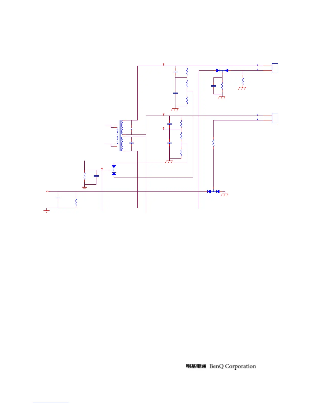
Fig.3
Fig.3 shows a feedback circuit consists of a lamp, R816, D805, R827 and C814. With the
lamp current through D805, a half sin-waveform voltage signal is produced. We may get the
Maximum value through R827 and C814.
After OZ9933 gets the feedback voltage signal from PIN14, the duty of the PWM driver
outputs is decided.
 Loading...