13
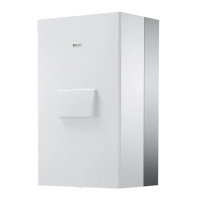
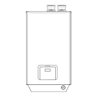
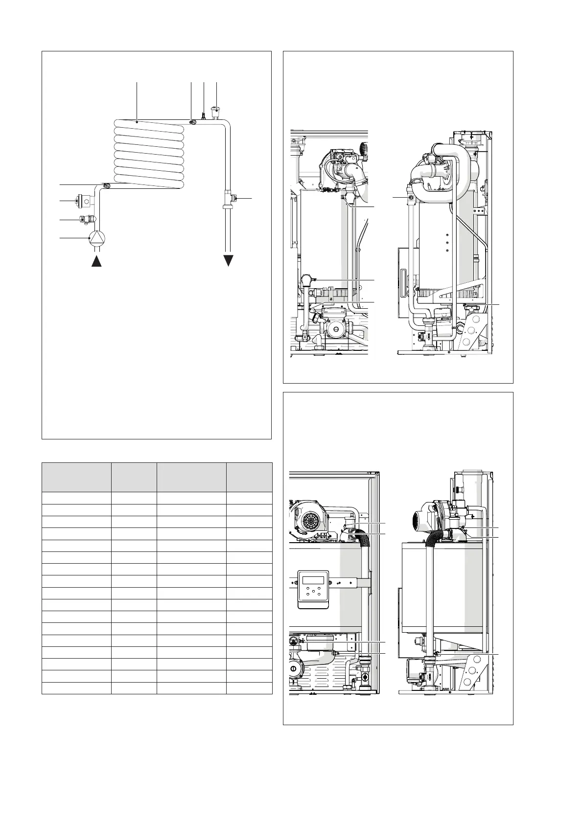
1.9 Water circuit
1
Heat exchanger
2
Circulator (only for models POWER MAX 50 P DEP -
POWER MAX 80 P)
3
Drain cock
4
Minimum pressure switch
5
NTC return probe
6
NTC delivery probe
7
Safety thermostat temperature sensor
8
Automatic bleed valve
9
Flow-meter
MI
Central heating ow
RI
Central heating return
Values of NTC probes' resistors with changing temperatures.
Temperature °C
Tolerance test
±10%
Resistor Ω
Temperature °C
Tolerance test
±10%
Resistor Ω
-40 191908 45 4904
-35 146593 50 4151
-30 112877 55 3529
-25 87588 60 3012
-20 68471 65 2582
-15 53910 70 2221
-10 42739 75 1918
-5 34109 80 1663
0 27396 85 1446
5 22140 90 1262
10 17999 95 1105
15 14716 100 970
20 12099 105 855
25 10000 110 755
30 8308 115 669
35 6936 120 594
40 5819 125 529
1.10 Positioning the temperature sensors
Probes placed on the related sockets of the thermal module
(POWER MAX 50 P DEP - POWER MAX 50 P):
1
Exhaust ue probe
2
Safety thermostat
3
CH ow temperature sensor
4
Return probe
3
4
1
2
Front view Side view
Probes placed on the related sockets of the thermal module
(POWER MAX 65 P ÷ POWER MAX 150):
1
Exhaust ue probe
2
Safety thermostat
3
CH ow temperature sensor
4
Return probe
3
2
1
4
Front view Side view
 Loading...