Do you have a question about the Beretta POWER PLUS and is the answer not in the manual?
Statement of compliance with EU directives and standards for POWER PLUS boilers.
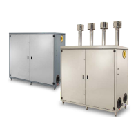
List of POWER PLUS boiler models and their corresponding identification codes.
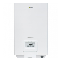
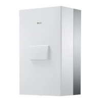
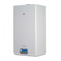
Overview of the POWER PLUS boiler, its features, and capabilities.
Details on the safety thermostats, probes, and systems fitted on the boiler.
Information provided on the boiler's packaging label for identification.
Details shown on the boiler's rating plate for technical specifications.
Diagram showing the internal layout and numbered components of the 50 M model.
Diagram showing the internal layout and numbered components of 100 M/S models.
Schematic showing the water flow paths and key components within the boiler.
Graph illustrating the pressure drop in the boiler as a function of flow rate.
Instructions for correctly positioning central heating and flue gas probes.
Details on system pump configurations for heating circuits.
Diagram showing system setup using injection pumps for heating circuits.
Diagram showing system setup with a ring circulator and thermostatic valves.
Electrical schematic for the master board and connections on POWER PLUS 50M/100M/100M DEP.
Electrical schematic for slave boards and connections on POWER PLUS 50M/100M/100M DEP.
Electrical schematic for the master board and connections on POWER PLUS 100 S/100 S DEP.
Electrical schematic for slave boards and connections on POWER PLUS 100 S/100 S DEP.
Diagrams showing the layout of buttons and indicators for different boiler models.
Explanation of the functions managed by the control panel for boiler operation.
How to use the buttons on the control panel for setting modes and parameters.
Understanding the system status displayed on the 3-digit display.
How to scroll and view system values like temperatures and status in readout mode.
Procedure for changing user-adjustable setpoints for heating and DHW.
How to access monitor mode to check individual unit operating values.
Navigating and viewing parameters like temperature, fan speed, and pump status.
Procedure to enter installer programming mode using a password.
How to navigate and change installer-specific parameters.
How to enter and use test mode for checking boiler operation at different speeds.
Procedure for identifying and displaying error codes on the boiler.
How to reset permanent lockouts and system errors.
Contents of the boiler package and initial inspection upon receipt.
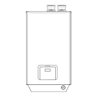
Physical dimensions and net/packaged weight for different POWER PLUS boiler models.
Instructions for manually tilting and lifting the boiler, avoiding casing damage.
Specifications for the boiler room, including ventilation and clearance for operation.
Steps for securing the boiler to the wall using the provided bracket.
Details on fitting sizes for central heating flow/return and gas supply.
Procedure for connecting the condensate drain pipe to the sewerage system.
Procedure for cleaning existing systems before boiler installation.
Components included in the water connection kit for installations up to 100 kW.
Components included in the water connection kit for installations above 100 kW.
Checks for gas type, pipe cleanliness, and size for fuel supply connection.
Guidelines for installing flues and air intake pipes, including material and airtightness.
Details on the maximum allowed length for intake pipes and flues, including bend allowances.
Minimum compartment dimensions for installing flue pipes for single or multiple boiler setups.
Diagram and description of terminals for connecting probes, pumps, and room thermostats.
Recommendations for optimal placement of the outside probe for climate control.
Steps for fastening the probe to the wall and connecting its wires to the terminal block.
Procedure for filling the heating system and venting air from the boiler.
Steps to close valves and drain water from the boiler units.
Procedure for connecting a hose to the system return drain cock to empty the system.
Steps to turn on the main switch and heating units, and initial self-diagnosis.
Setting room thermostats and desired temperatures for initial boiler operation.
Checking boiler starts/stops, DHW temperature display, and thermostat settings.
Procedure for verifying the complete shutdown of the boiler by turning off the main switch.
Configuring high and low temperature circuits, including setpoints and climate control curves.
Setting the objective temperature for the high temperature circuit based on mode.
Setting the objective temperature for the low temperature circuit.
Setting the priority level between central heating circuits.
Setting the desired temperature for domestic hot water production.
Configuring the type of storage heater or rapid heat exchanger for DHW.
Setting the priority level for domestic hot water service over central heating.
Adjusting attenuation for the high temperature circuit with fixed setpoint or climate control.
Adjusting attenuation for the low temperature circuit with fixed setpoint or climate control.
Correcting the displayed outside temperature value using parameter 39.
Configuring the frost protection levels that start the pump and/or burner.
Setting cascading strategies for managing boiler output based on burner count.
Managing boiler output by controlling the maximum number of burners in a cascade.
Functions for burner ignition rotation and limitations on starts/stops.
Methods for manually controlling slave boards via eBUS or PC in case of master faults.
Using analogue input to calculate heat output demand for heating circuits.
Using analogue input to set temperature demand for heating circuits via PID control.
Parameters controlling the operation, timing, and hysteresis of the mixing valve.
Slave board shutdown conditions based on temperature limits and water circulation.
Steps to access the slave boards within the boiler control panel.
Procedure for configuring microswitches to set addresses for cascading setup.
Description of permanent (Type A) and automatic (Type E) errors on the master board.
List of errors requiring manual reset on slave boards, with causes and solutions.
List of errors on slave boards that deactivate automatically when the cause is removed.
Table of user-accessible parameters with their default settings and descriptions.
List of installer parameters accessible via password, covering DHW and CH settings.
List of installer parameters for low circuit, frost protection, gas type, and system settings.
Steps for converting the boiler from natural gas to LPG, including parameter changes.
Procedure for adjusting CO2 levels for maximum output using the fan assembly screw.
Procedure for adjusting CO2 levels for minimum output using the fan assembly screw.
Verifying CO2 values at maximum and minimum output after adjustments.
Steps for setting thermostats and leaving power on for temporary absence.
Procedure for turning off the boiler and closing valves for long-term non-use.
Explanation of why periodical servicing is essential for safety, efficiency, and longevity.
Instructions for cleaning the boiler casing, control panel, and painted parts.
Steps to take before starting internal cleaning operations, such as closing valves.
Steps to remove the front panel to access the control panel and internal components.
Locating and accessing the terminal block, master board, and slave boards.
Procedure for removing the control boards and their connectors.
Steps for removing the fan unit from the boiler's heat exchanger.
Steps to remove the burner and electrode plate for cleaning and inspection.
Procedure for removing and cleaning the condensate drain trap and its components.
Diagnosing and resolving issues related to gas smell and irregular combustion.
Troubleshooting delays in ignition, pulsating operation, and boiler soiling.
Diagnosing why the boiler doesn't start or reach operating temperature.
Troubleshooting thermal overload, system coldness, and pump faults.