INSTALLATION INSTRUCTION
34
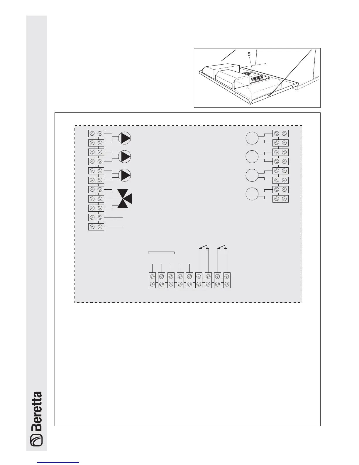
- Identify the terminal block (5) and make the connec-
tions, as in the diagram shown below..
Pbas (*) Low temperature
system pump
PB (*)
28
27
26
25
24
23
22
21
20
19
18
1
2
3
4
5
6
7
8
DHW pump
PZ1 (*)
High Temperature
system pump
PZ2 (*) Loop pump or
VM (*)
Mixing valve
SB
Storage heater probe
SZ1
Probe in zone 1,
high temperature
SE
Outside probe
Contact for
alarm signal
17
16 15 14
13 12
11
10 9
TA1
High temperature
room thermostat
TA2
Low temperature
room thermostat
TERMINAL BLOCK INSIDE THE MASTER CONTROL PANEL
SZ2
Probe in zone 2,
low temperature
(*) 230V~50Hz
0-10V
analogue
input
CR
Remote
control
IA
24V
COM
BUS
b The following measures are compulsory:
1 - the use of an omnipolar thermal overload
switch, mains disconnecting switch, com-
pliant with the CEI-EN standards (minimum
contact opening 3 mm);
2 - respect the connection L (Line) - N (Neutral).
Leave the earth wire around 2 cm longer than
the power wires;
3 - use wires with a cross-section greater than or
equal to 1.5 mm2, complete with pointed end
terminals;
4 - refer to the wiring diagrams in this booklet for
any operations on the electrical system;
5 - connect the appliance to an effective earth
system.
b
The pumps should be connected by instal-
ling suitable contactors with manual emer-
gency operation.
a
The gas and/or water pipes must not be
used to earth the appliance.
a
The power supply and room thermostat
cables must not run near hot surfaces
(outlet pipes).
The manufacturer is not liable for any dama-
ge due to the failure to earth the appliance
and to observe the information provided on
the wiring diagrams.
 Loading...