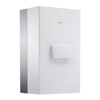
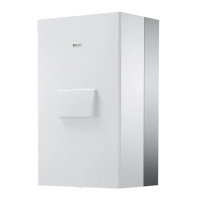
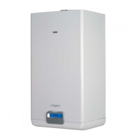
INSTALLATION INSTRUCTION
8
12 34
6
7
8
5
10
9
11
24
22
23
24
22
23
21
19
20
18
12 34 12 34
6
7
5
10
9
11
14 13 12 15
17
16
21
19
20
18
17
16
14 13 12 1514 13 12 16 17
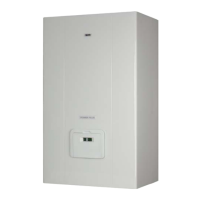
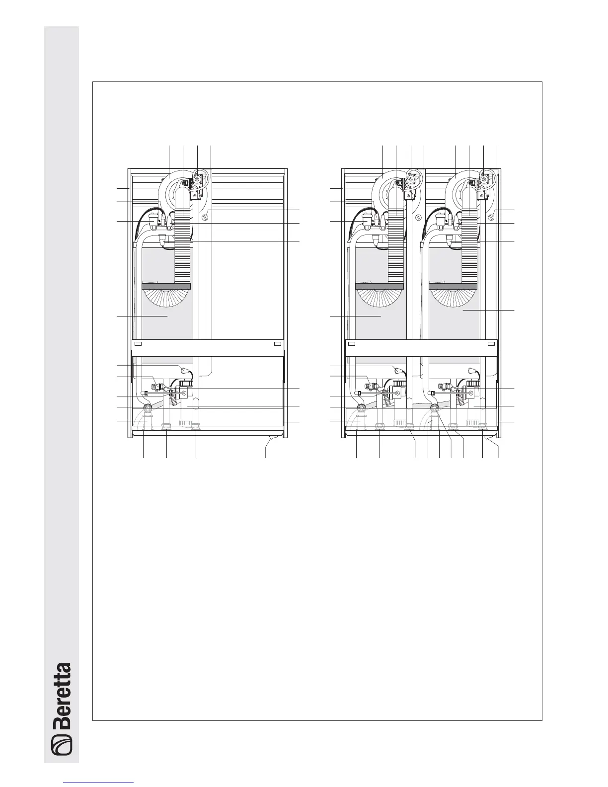
1 - Fan
2 - Combustion air intake fitting
3 - Gas valve
4 - Flue gas outlet fitting
5 - Flue gas analysis test point
6 - Outlet probe
7 - Safety thermostat
8 - SECOND combustion chamber
(models 100 M, 100 M DEP,
100 S and 100 S DEP)
9 - Return probe
10 - Condensate collection drain trap
11 - Control panel (90° rotation)
12 - Gas supply
POWER PLUS 50 M POWER PLUS 100 M - 100 M DEP
100 S - 100 S DEP
13 - Central heating return inlet
14 - Central heating flow outlet
15 - Main switch
16 - Safety valve (5,4 bar)
17 - Water differential pressure switch
18 - Drain cock
19 - Flue gas probe
20 - FIRST combustion chamber
21 - Automatic vent valve
22 - Ignition / detection electrode
23 - Panelling
Structure