INSTALLATION INSTRUCTION
18
1
12
11
131415 1612 13 14
1
12
23 5 76810911
131415 1612 13 14
1235768109
15 1612 13 14
4
4
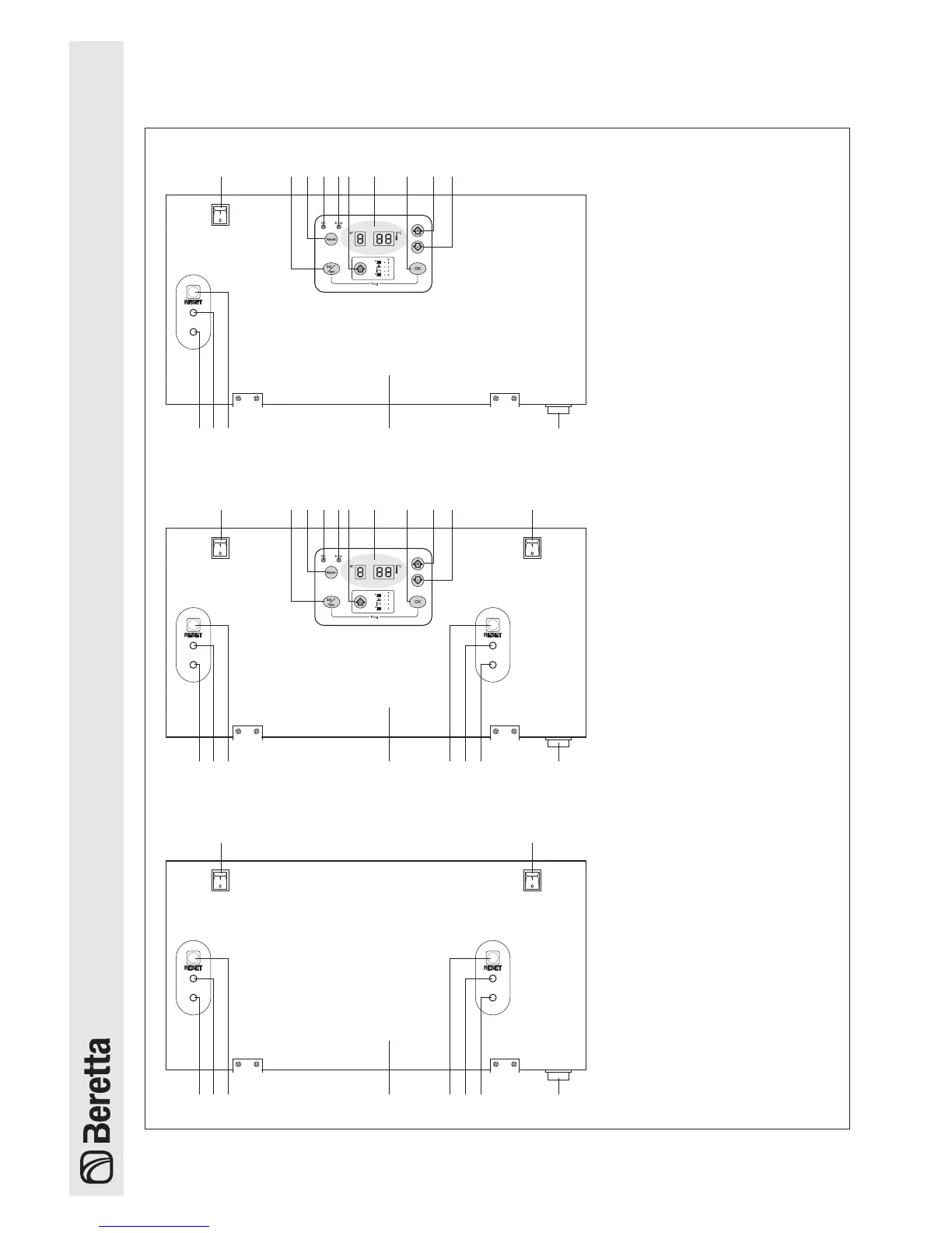
1 - FIRST heating unit switch
2 - Button for selecting
the operating mode
3 - Reset button (Master)
4 - Boiler lockout signal
5 - Button for selecting
the parameters
6 - Display
7 - Save button
8 - Button to increase values
9 - Button to decrease values
10 - SECOND heating unit switch
11 - Slave power supply signal
- slow flashing = stand-by
- rapid flashing = ignition cycle
- fixed light = flame detected
12 - Slave lockout signal
13 - Reset button (Slave)
14 - Instrument panel
15 - Main boiler switch
POWER PLUS 50 M
POWER PLUS 100 M - 100 M DEP
POWER PLUS 100 S - 100 S DEP
Control Panels