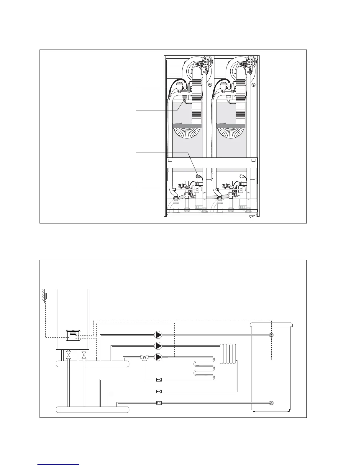
THE POWER PLUS Boiler
does not come with a pump, which must be installed in the system.
When choosing the pump, refer to the following system diagrams.
Confi guration with distribution pumps
Boiler discharge head: 7 mWC
Boiler fl ow-rate: 2 m3/h for each heating unit.
Also consider the pressure drops in the individual circuit.
PB - DHW pump
PZ1 - Pump in zone 1
(high temperature)
PZ2 - Pump in zone 2
(low temperature)
V2 - Two-way valve
(accessory)
SZ1 - Probe in zone 1
SZ2 - Probe in zone 2
SB - DHW probe
SE - Outside probe
b
Install probes SZ1, SZ2 and SB in a probe socket (outside of the boiler).
Positioning the Probes
Pumps






 To Next Page