INSTALLATION INSTRUCTION
20
DISPLAY MODE
The red LED (see ref. 5 on page 18) comes on in the event of faults that cause the permanent lockout of a heating unit
(normal operation is reset only by pressing the Master or Slave reset button).
The 3 digits with seven segments display the status of the system:
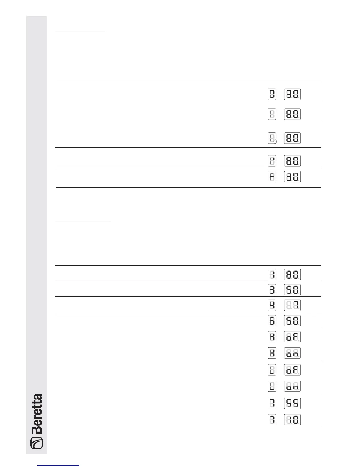
Status of the system Display
No central heating or DHW demand.
The two digits on the right display the outlet temperature T1. E.g.: T1 = 30°C
Demand from circuit no.1 or from circuits 1 and 2 together.
The two digits on the right display the outlet temp. T1. E.g.: T1 = 80°C
Demand from the DHW circuit or simultaneous operation.
The two digits on the right display the outlet temp. T1 E.g.: T1 = 80°C.
The decimal point after the 1st digit on the left flashes
Demand from the 2nd circuit
The two digits on the right display the outlet temperature T1. E.g. T1 = 80°C.
READOUT MODE
(TEMPERATURE VALUES AND OPERATING STATUS OF THE VARIOUS CIRCUITS)
Press the “[” button to scroll forwards and display the values set for the individual circuits.
The values listed below will be displayed in sequence when pressing the “[” button.
Value displayed Display
1 Outlet temperature T1 in the high temperature circuit. E.g. : T1 = 80°C
2 DHW temperature T3. E.g.: storage heater temperature = 50°C
3 Outside temperature T4. E.g. T4 = 7°C
4 Outlet temperature in 2nd circuit or low temperature circuit T6
5 Room thermostat in the 1st circuit, closed or open.
OFF = contact open
ON = contact closed
6 Room thermostat in the 2nd circuit, closed or open
OFF = contact open
ON = contact closed
7 0-10V analogue input
E.g. 5.5V, 10V
Anti-frost function