EasyManua.ls Logo

Beretta POWER PLUS - Wiring Diagrams; POWER PLUS 50 M;100 M;100 M DEP Wiring Diagram (Part 1)

Beretta POWER PLUS
72 pages
Print Icon
To Next Page IconTo Next Page
To Previous Page IconTo Previous Page
Loading...
INSTALLATION INSTRUCTION
14
15
Bus
16
Com.
87
2
1
2
3
1
J9
23
22
21
Valv.Mix
OFF
0
20
Alarm
ON
1
18
19
J8
9
17
24V
7
6
8
1314
Input
Analogic
NTC
Circ. 2
10 9
7
6
8
12
Circ.2
11
56
J12
4321
6
2
3
4
5
J10
28
27
Pump
25
24
26
Pump 3
Pump
1
2
5
4
3
J11
NTC
1
2
NTC
NTC
4
5
3
a
m
gv
gv
gv
gv
J4
J2
J8
J10
R4
2
3
J3
J6
J5
J7
F1
Fuse
3.15 A
1
R6
R5
MC
R3 R2
J12
2
BUS J14
1
R1
4
3
T1
1
2
J1
PC
BARCODE
J11 11
gv
gv
m
a
gv
gv
gv
m
a
m
a
MASTER
230V~50Hz
PB
PZ1
PZ2
VM
SZ1
SB
SE
SZ2
TA1TA2
IG
J11 4
J11 12
J11 5
J11 13
J11 6
J11 14
J11 7
J11 7
J11 14
J11 6
J11 13
J11 5
J11 12
J11
4
J11 11
IACR
J11 3
J11 10
J12 2
J12 3
J12 4
J12 4
J12 3
J12 2
J11
8
J11
1
J11
9
J11
2
J11
10
J11
3
J10 6
J10
5
J10
4
J10
3
J10
2
J10
1
J8
5
J8
4
J8
3
J8
2
J8
1
J10 6
J10 5
J10 4
J10 3
J10 2
J10 1
J9 3
J9 2
J9 1
J8 2
J8 1
3
4
7
14
1
8
J11
Main earth
pole
Joint with
sheath
Off - Max. valve
Line Pump 1
Neutral pump 1
Line DHW pump
Neautral DHW pump
Neutral Max. valve
Line Pomp 3
Neutral pump 3
On - Max. valve
Alarm
Common
Neutral 230V a.c.
Line 230V a.c.
Earth
Earth
Earth
Earth
Ebus remote cont.
24V remote cont.
Common
Analogic Input
Common
Common
T. circ. 1
Common
R .
R .
T. circ. 2
Line
Earth
Neutral
Climate NTC
Common
Outlet NTC circ. 2
Outlet NTC circ. 1
Common
Common
DHW NTC
Common
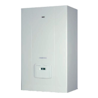
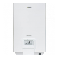
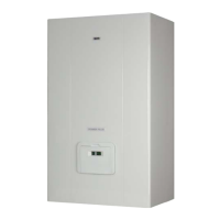
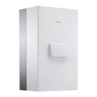
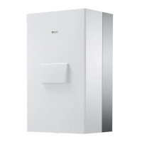
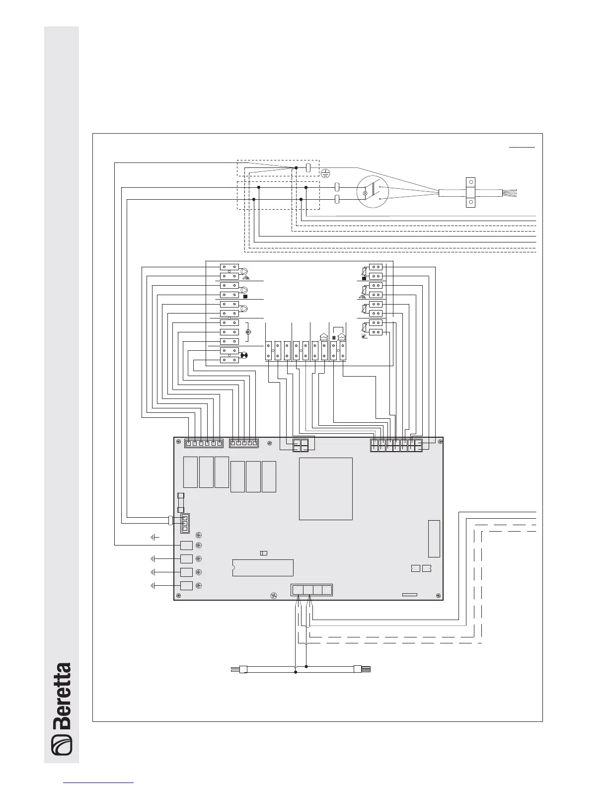
The control panel on
POWER PLUS
models 50 M, 100 M and 100 M DEP contains one master board and one or two slave
boards, depending on the output of the boiler. Models 100 S and 100 S DEP contain just two slave boards. If connecting a
series of boilers in cascading, the master board on the
POWER PLUS
50 M, 100 M or 100 M DEP manages all the boards
on the
POWER PLUS
100 S or 100 S DEP boilers via BUS.
Bus line with male
connector for connection
to another models 100 S
or 100 S DEP boiler.
Bus line with female
connector for connection
to another model 100 S
or 100 S DEP boiler.
POWER PLUS 50 M - 100 M - 100 M DEP part 1
Wiring Diagrams